
Subscribe to Our Youtube Channel
Related Manuals for Cypress I2C-USB


Summary of Contents for Cypress I2C-USB
- Page 1 CY3240-I2USB I2C-USB Bridge Guide Doc. # 001-66660 Rev.** Cypress Semiconductor 198 Champion Court San Jose, CA 95134-1709 Phone (USA): 800.858.1810 Phone (Intnl): 408.943.2600 http://www.cypress.com [+] Feedback...
- Page 2 Code protection does not mean that we are guaranteeing the product as "unbreakable." Cypress is willing to work with the customer who is concerned about the integrity of their code. Code protection is constantly evolving.
-
Page 3: Table Of Contents
4.2.4 GPIO Pins ......................27 4.2.5 I2C Slave Interface Connector ...............28 4.2.6 Demo Target Board ..................29 5. Example Projects Example Project 1: I2C-USB Demo Target Board Project.........31 5.1.1 Project Description ..................31 5.1.2 Hardware Connections...................32 5.1.3 I2C-USB Demo Target Board Flowchart ............33 5.1.4 Verify Output ....................34... - Page 4 A.1.2 Demo Target Board Schematic..............42 I2C-USB Bridge Board Layout................... 43 A.2.1 Demo Target Board Layout................43 BOM .......................... 44 A.3.1 I2C-USB Bridge BOM Rev. E ................ 44 A.3.2 Demo-Target Board R..................45 CY3240-I2USB I2C-USB Bridge Guide, Doc. # 001-66660 Rev.** [+] Feedback...
-
Page 5: Introduction
■ ■ CY3240-I2USB kit CD Inspect the contents of the kit. If any parts are missing, contact your nearest Cypress sales office for further assistance. Bridge Control Panel Software Bridge Control Panel is installed along with PSoC Programmer and enables the bridge to communi- cate with the PC. -
Page 6: Additional Learning Resources
Click the File icon and then click Open. Displays an equation: Times New Roman 2 + 2 = 4 Text in gray boxes Describes cautions or unique functionality of the product. CY3240-I2USB I2C-USB Bridge Guide, Doc. # 001-66660 Rev.** [+] Feedback... -
Page 7: Getting Started
2. Click Install CY3240-I2USB Bridge Kit to start the installation, as shown in Figure 2-1. Figure 2-1. CY3240-I2USB Menu Note If auto-run does not execute, double-click cyautorun.exe file on the root directory of the CD, as shown in Figure 2-2. CY3240-I2USB I2C-USB Bridge Guide, Doc. # 001-66660 Rev.** [+] Feedback... - Page 8 6. On the Product Installation Overview screen, select the installation type that best suits your requirement. The drop-down menu has three options: Typical, Complete, and Custom, as shown in Figure 2-4. 7. Click Next to start the installation. CY3240-I2USB I2C-USB Bridge Guide, Doc. # 001-66660 Rev.** [+] Feedback...
- Page 9 9. A green checkmark appears against every package that is downloaded and installed, as shown Figure 2-5. 10.Wait until all the packages are downloaded and installed successfully. Figure 2-5. Installation Page CY3240-I2USB I2C-USB Bridge Guide, Doc. # 001-66660 Rev.** [+] Feedback...
-
Page 10: Psoc Designer
Figure 2-6. Installation Complete Page After the software installation, verify that you have all hardware and drivers set up for the I2C-USB kit by connecting the bridge to your PC via its USB interface. Because this is the first time you have connected this board to the PC, initial drivers are installed. - Page 11 Getting Started Figure 2-7. PSoC Designer Interconnect View Note For more details on PSoC Designer, see the PSoC Designer IDE Guide located at: <InstalledDirectory>:\Cypress\PSoC Designer\<version>\Documentation. CY3240-I2USB I2C-USB Bridge Guide, Doc. # 001-66660 Rev.** [+] Feedback...
-
Page 12: Psoc Programmer
4. Close PSoC Programmer. Bridge Control Panel The Bridge Control Panel is used with CY3240 I2C-USB Bridge to enable communication with I2C slave devices. This program is used to configure I C devices and also to acquire and process data received from I2C slave devices. -
Page 13: Install Hardware
Figure 2-9. Selecting the Bridge Note For more information, go to Bridge Control Panel > Help > Help Contents. Install Hardware No hardware installation is required for this kit. CY3240-I2USB I2C-USB Bridge Guide, Doc. # 001-66660 Rev.** [+] Feedback... - Page 14 Getting Started CY3240-I2USB I2C-USB Bridge Guide, Doc. # 001-66660 Rev.** [+] Feedback...
-
Page 15: Kit Operation
The USB communication function uses two 64-byte packets: one for input data flow and the other for output data flow. The maximum bandwidth of this configuration is 64 bytes. This is sufficient for most I2C-USB bridge applications (Figure 3-1). Figure 3-1. I2C-USB Bridge CY3240-I2USB I2C-USB Bridge Guide, Doc. # 001-66660 Rev.** [+] Feedback... -
Page 16: Connect Bridge To Device
5. Open the Bridge Control Panel from the PC to work with the bridge. 3.2.1 Program I2C-USB Bridge The CY3240 I2C-USB Bridge can be programmed using a MiniProg at the programming header of the bridge. To use MiniProg, use the ISSP Programming Header (J2) on the board as highlighted in Figure 3-4. -
Page 17: Connect Demonstration Board To Bridge
Run Demonstration Board Test The demonstration board has built-in temperature sensor and photodiode. The measurement results of these are sent over I 1. Open the Variable Setting dialog box from the Chart menu. CY3240-I2USB I2C-USB Bridge Guide, Doc. # 001-66660 Rev.** [+] Feedback... - Page 18 [Enter] to send the command. Repeat for the second command line. Observe that, on sending the first command, the LED1 turns off. The second command reduces the LED intensity by 50 percent. CY3240-I2USB I2C-USB Bridge Guide, Doc. # 001-66660 Rev.** [+] Feedback...
- Page 19 This makes data collection easier. The data received from slave can be viewed either graphically or in a tabular form. 6. Click the Chart tab to view data graphically, as shown in Figure 3-9. CY3240-I2USB I2C-USB Bridge Guide, Doc. # 001-66660 Rev.** [+] Feedback...
- Page 20 Figure 3-9. Bridge Control Panel Graphical Screen View 7. Click the Stop button to stop scanning. 8. Click the Table tab to view data in a tabular form, as shown in Figure 3-10. CY3240-I2USB I2C-USB Bridge Guide, Doc. # 001-66660 Rev.** [+] Feedback...
- Page 21 Save Receive Data - To save received data shown on the status window of Bridge Control Panel. ■ Go to Bridge Control Panel Help from the Help menu for more information on the Bridge Control Panel and iic command format. CY3240-I2USB I2C-USB Bridge Guide, Doc. # 001-66660 Rev.** [+] Feedback...
- Page 22 Kit Operation CY3240-I2USB I2C-USB Bridge Guide, Doc. # 001-66660 Rev.** [+] Feedback...
-
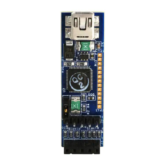
Page 23: Hardware
USB Mini B Connector (Communication and I2C Slave PSoC Power Supply of Connector CY8C24894 3.3V/5V) GPIO Pins Demo target board consists of: CY8C21123 chip ■ ■ Photodiode ■ ■ ISSP programming header/data connector CY3240-I2USB I2C-USB Bridge Guide, Doc. # 001-66660 Rev.** [+] Feedback... -
Page 24: Functional Description
CY8C21123 Functional Description The I2C-USB Bridge is connected to the PC in the same way as an HID device. It requires no additional driver when connected to a PC installed with Windows. This I2C-USB Bridge works as a master in the I C bus and is controlled by the PC program via USB. -
Page 25: Psoc Cy8C24849 Chipset
3.3 V or 5 V to target board. These plugs are always oriented down- stream towards the USB device. It has SN65220, a single transient voltage suppressor, to provide electrical noise transient protection to USB port. CY3240-I2USB I2C-USB Bridge Guide, Doc. # 001-66660 Rev.** [+] Feedback... -
Page 26: Issp Programming Header
Table 4-1. ISSP Programming Header Connection Details Pin No Connection Description +V Device To supply voltage to the bridge Ground pin of the bridge Interrupt pin Serial data line Serial clock line CY3240-I2USB I2C-USB Bridge Guide, Doc. # 001-66660 Rev.** [+] Feedback... -
Page 27: Gpio Pins
Analog column mux input P0[5] Analog column mux input and column output P0[3] Analog column mux input and column output P0[1] Analog column mux input P2[7] GPIO P2[5] GPIO TP13 P2[2] GPIO CY3240-I2USB I2C-USB Bridge Guide, Doc. # 001-66660 Rev.** [+] Feedback... -
Page 28: I2C Slave Interface Connector
(High) is 0.6 ■ times V (if source current is 0.02 mA) and V (Low) is 0.4 V SN721 An array of SCR/diode bipolar structure for ESD and over-voltage protection ■ CY3240-I2USB I2C-USB Bridge Guide, Doc. # 001-66660 Rev.** [+] Feedback... -
Page 29: Demo Target Board
I2C master. Table 4-3. CY8C21123 Pin Connectivity Pin No. Port No Description P0[4] LED1 P0[2] LED2 P0[5] Photo-diode P1[0] Voltage supply P1[1] Ground P0[3] Interrupt Serial clock Serial data CY3240-I2USB I2C-USB Bridge Guide, Doc. # 001-66660 Rev.** [+] Feedback... - Page 30 Hardware Figure 4-9. Demo Board Chip Schematic CY3240-I2USB I2C-USB Bridge Guide, Doc. # 001-66660 Rev.** [+] Feedback...
-
Page 31: Example Projects
Example Projects All example projects are available in the CY3240-I2USB kit CD or at the following location: <Installed_directory>:\Cypress\CY3240-I2USB\Firmware Example Project 1: I2C-USB Demo Target Board Project 5.1.1 Project Description This example project demonstrates the data transfer between target board and host. The target board has a photodiode to measure light intensity and temperature values, which are acquired by the PSOC device (CY8C21123) to transmit to host. -
Page 32: Hardware Connections
Example Projects 5.1.2 Hardware Connections Figure 5-1. Functional Blocks CY3240-I2USB I2C-USB Bridge Guide, Doc. # 001-66660 Rev.** [+] Feedback... -
Page 33: I2C-Usb Demo Target Board Flowchart
Example Projects 5.1.3 I2C-USB Demo Target Board Flowchart CY3240-I2USB I2C-USB Bridge Guide, Doc. # 001-66660 Rev.** [+] Feedback... -
Page 34: Verify Output
This project uses the following modules: CMPRG: Used to compare the data programmable reference threshold. PWRFB: Used to set the power level for this application. TIMER8: Used to wake up the application from sleep mode. CY3240-I2USB I2C-USB Bridge Guide, Doc. # 001-66660 Rev.** [+] Feedback... -
Page 35: Hardware Connections
Example Projects 5.2.2 Hardware Connections Figure 5-3. Functional Bocks CY3240-I2USB I2C-USB Bridge Guide, Doc. # 001-66660 Rev.** [+] Feedback... -
Page 36: I2C-Usb Bridge Flowchart
Example Projects 5.2.3 I2C-USB Bridge Flowchart CY3240-I2USB I2C-USB Bridge Guide, Doc. # 001-66660 Rev.** [+] Feedback... - Page 37 Example Projects CY3240-I2USB I2C-USB Bridge Guide, Doc. # 001-66660 Rev.** [+] Feedback...
-
Page 38: Verify Output
Example Projects 5.2.4 Verify Output When connected to the demonstration board, LED (green) blinks on the bridge indicating transfer operation between the bridge and PC. Figure 5-4. Verify Output CY3240-I2USB I2C-USB Bridge Guide, Doc. # 001-66660 Rev.** [+] Feedback... -
Page 39: Appendix
Appendix Schematic A.1.1 I2C-USB Bridge Schematic Figure A-1. Reverse Current Protection Schematic CY3240-I2USB I2C-USB Bridge Guide, Doc. # 001-66660 Rev.** [+] Feedback... - Page 40 Figure A-2. USB Connection with Voltage Suppressor Schematic Figure A-3. Diode Schematic CY3240-I2USB I2C-USB Bridge Guide, Doc. # 001-66660 Rev.** [+] Feedback...
- Page 41 Figure A-4. Voltage Regulator Schematic CY3240-I2USB I2C-USB Bridge Guide, Doc. # 001-66660 Rev.** [+] Feedback...
-
Page 42: Demo Target Board Schematic
Figure A-5. PSoC CY8C24894 Schematic A.1.2 Demo Target Board Schematic Figure A-6. Demo Board Schematic CY3240-I2USB I2C-USB Bridge Guide, Doc. # 001-66660 Rev.** [+] Feedback... -
Page 43: I2C-Usb Bridge Board Layout
I2C-USB Bridge Board Layout Figure A-7. Top View Figure A-8. Bottom View A.2.1 Demo Target Board Layout Figure A-9. Top View CY3240-I2USB I2C-USB Bridge Guide, Doc. # 001-66660 Rev.** [+] Feedback... -
Page 44: Bom
TVS Array ESD 6 Input 8-SOIC Littelfuse Inc SP721ABG * 000 RES 0.0 OHM 1/8W 5% 0805 SMD Rohm MCR10EZHJ000 * 000 RES 0.0 OHM 1/8W 5% 0603 SMD Rohm MCR03EZPJ000 J1 * Shunt 929950-00 CY3240-I2USB I2C-USB Bridge Guide, Doc. # 001-66660 Rev.** [+] Feedback... -
Page 45: Demo-Target Board R
Microsemi Inc LX1972IBC D2, D3 LED RED CLEAR 0805 SMD LITE-ON INC LTST-C170CKT 160-1176-2-ND IC PSoC 21x23 8SOIC Cypress Semiconductor CY8C21123-24SXI CONN HEADER .100 SNGL STR 5POS Samtec TSW-105-07-T-S SAM1035-05-ND CY3240-I2USB I2C-USB Bridge Guide, Doc. # 001-66660 Rev.** [+] Feedback... - Page 46 CY3240-I2USB I2C-USB Bridge Guide, Doc. # 001-66660 Rev.** [+] Feedback...
Need help?
Do you have a question about the I2C-USB and is the answer not in the manual?
Questions and answers