Reliable H PrePak Instructions For Installation, Operation Care And Maintenance
Preaction system 1 1/2" (40mm) single and double interlock
Hide thumbs
Also See for H PrePak:
- Instructions for installation, operation care and maintenance (24 pages) ,
- Instructions for installation and operation manual (22 pages) ,
- Bulletin (17 pages)
Advertisement
Quick Links
Advertisement

Related Manuals for Reliable H PrePak


Summary of Contents for Reliable H PrePak
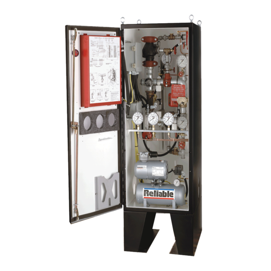
- Page 1 Bulletin 723 Rev. Model H PrePak Preaction System 1½” (40mm) Instructions for Single Interlock Installation, Operation, Double Interlock Care and Maintenance 10 PSI (0.7 bar) Pneumatic Supervising Pressure Reliable Automatic Sprinkler Co., Inc., 103 Fairview Park Drive, Elmsford, New York 10523...
-
Page 2: General Description
The Model H PrePaK can be used in both single and double in- into the control panel. terlock applications. Reliable Single and Double Interlock Preaction... - Page 3 Figure 1 — Installation Dimension...
-
Page 4: Technical Data
3. Only Class A method of wiring detectors shall be used. the Reliable Model H 1½” (40mm) PrePaK must be UL and/or ULC For Double-Interlock Preaction Systems: Listed, as applicable. - Page 5 RED OUTPUT LED STEADY: ABORT ZONE 1 OUTPUT 1 ZONE 2 OUTPUT 2 ZONE 3 OUTPUT 3 PROGRAM ZONE 4 OUTPUT 4 MODE MODE AC POWER SUP 1/ABORT SCROLL-UP POWER TBL SUPERVISORY 2 BUZZER SILENCE SYSTEM TBL COMMON ALARM LAMP SUP TBL ALARM SILENCE TEST...
- Page 6 Figure 3 — Wiring Diagram...
-
Page 7: Maintenance
System Operation (Single Interlock) valve. Bulletin 251 provides information on the Model A-2 Pressure To activate the Reliable Model H 1½” (40mm) PrePaK in a single Maintenance Device. Bulletin 806 describes the Model G Right- interlock application, an electrical detector (two detectors with cross- Check™... - Page 8 Resetting Double Interlock Systems Testing Detection System Without Causing Refer to Figure 1. Water Flow (Single Interlock) 1. Close the supervised valve controlling water supply to the Mod- Refer to Figure 1. el H Riser Assembly and shut off the system’ s air supply at the 1.
- Page 9 RED OUTPUT LED STEADY: ABORT ZONE 1 OUTPUT 1 ZONE 2 OUTPUT 2 ZONE 3 OUTPUT 3 PROGRAM ZONE 4 OUTPUT 4 MODE MODE AC POWER SUP 1/ABORT SCROLL-UP POWER TBL SUPERVISORY 2 BUZZER SILENCE SYSTEM TBL COMMON ALARM LAMP SUP TBL ALARM SILENCE TEST...
- Page 10 Figure 5 — Wiring Diagram...
- Page 11 Figure 6 — Wiring Diagram...
- Page 12 Figure 7 — Wiring Diagram...
- Page 13 Potter Program #6 Single Interlock Programming Instructions (Single Hazard, 2 Alarm Zones, 1 Waterfl ow Zone, and 2 Supervisory Zones) 1. Apply power to panel. 5. Press the FUNCTION button until the display reads “PRO- 2. Slide the program switch down. GRAM ##”...
- Page 14 Figure 8 — Wiring Diagram...
- Page 15 Potter Program #7 Single Interlock Programing Instructions (Single Hazard - Cross-Zoned, 2 Alarm Zones, 1 Waterfl ow Zone and 2 Supervisory Zones) 5. Press the FUNCTION button until the display reads “PRO- 1. Apply power to panel. GRAM ##” (the second “#” character refers to the current pro- 2.
- Page 16 Figure 9 — Wiring Diagram...
- Page 17 Potter Program #9 Double Interlock Programming Instructions (Single Hazard, Cross Zoned, 2 Alarm Zones (1 Detection & 1 Low Air), 1 Waterfl ow Zone, and 1 Supervisory Zone) 5. Press the FUNCTION button until the display reads “PRO- 1. Apply power to the panel. GRAM ##”...
- Page 18 Figure 10 — Wiring Diagram...
- Page 19 Potter Program #10 Double Interlock Programming Instructions (Single Hazard, Cross Zoned, 3 Alarm Zones (2 Detection & 1 Low Air), 1 Waterfl ow Zone, and 1 Supervisory Zone) 1. Apply power to the panel. 5. Press the FUNCTION button until the display reads “PRO- 2.
- Page 20 Figure 6 ¾ Double Interlock Preaction, Component Identification...
- Page 21 Custom Program #1 11. Press the SELECT button until the display reads “PROGRAM (For New York City Compliance) #0.” Single Interlock Programming Instructions for 12. Press the SET button. New York City Compliance (Single Hazard, 2 Alarm 13. Press the FUNCTION button until the display reads “OUTPUT Zones, 1 Waterfl...
- Page 22 Figure 12 — Wiring Diagram...
-
Page 23: Ordering Information
Air Compressor Voltage Example: 15 - 1 - 1 1½” (40 mm) Model H PrePaK Assembly, 1/6 Hp Air Compressor Factory Wired to 120 VAC @ 60 Hz, and Potter PFC- 4410-RC Releasing/Control Panel. SOLENOID VALVE INSPECTIONS, TESTS AND MAINTENANCE WARNING: THE OWNER IS RESPONSIBLE FOR MAINTAINING THE FIRE PROTECTION SYSTEM IN PROPER OPERATING CONDITION. - Page 24 The equipment presented in this bulletin is to be installed in accordance with the latest published Standards of the National Fire Protection Association, Factory Mutual Research Corporation, or other similar organizations and also with the provisions of governmental codes or ordinances whenever applicable. Products manufactured and distributed by Reliable have been protecting life and property for almost 100 years. Manufactured by Recycled Reliable Automatic Sprinkler Co., Inc.
Need help?
Do you have a question about the H PrePak and is the answer not in the manual?
Questions and answers