Reliable DDX PrePaK Instructions For Installation, Operation Care And Maintenance
Type f; preaction system; 2” (50mm), 21 /2” (65mm), 3” (80mm), 4” (100mm), 6” (150mm) & 8” (200mm); double interlock; electric/pneumatic release
Hide thumbs
Also See for DDX PrePaK:
Table of Contents
Advertisement
Quick Links
Instructions for
Installation, Operation,
Care and Maintenance
10 psi - 26 psi (0.7 bar - 1.8 bar) Recommended Supervisory Pressure
Reliable Automatic Sprinkler Co., Inc., 103 Fairview Park Drive, Elmsford, New York 10523
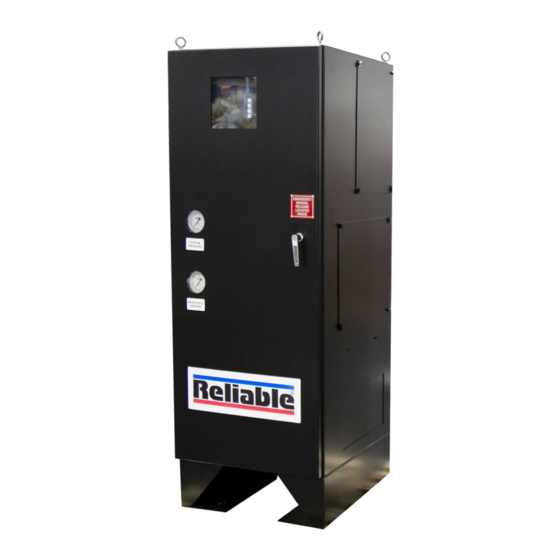
Model DDX PrePaK, Type F
Preaction System
2" (50mm), 2
1
4" (100mm), 6" (150mm) & 8" (200mm)
Double Interlock
Electric/Pneumatic Release
Contents
Diagrams:
Assembly Dimensions
Bulletin 747
/
" (65mm), 3" (80mm),
2
Page
C
Rev.
2
2
4
5
7
7
8
3
10
11
12-14
15-16
17
18-23
24-27
28-30
Advertisement
Table of Contents

Related Manuals for Reliable DDX PrePaK


Summary of Contents for Reliable DDX PrePaK
-
Page 1: Table Of Contents
Potter PFC-4410-RC Releasing Control Panel Terminal Box Wiring Factory Installed Electrical Devices 12-14 Detector Circuit Wiring 15-16 Output Device Wiring System Setup 18-23 Potter Panel Programming 24-27 Ordering Information 28-30 Reliable Automatic Sprinkler Co., Inc., 103 Fairview Park Drive, Elmsford, New York 10523... -
Page 2: General Description
VAC electrical power connections are required. Note: The lock applications, the sprinkler system is pressurized (su- Type F Model DDX PrePaK is available with its air compres- pervised) with air provided by the optional factory-installed sor and releasing/control panel wired for a 120 VAC / 60Hz air compressor (or on-site Nitrogen supply) and is monitored or for a 220 VAC / 50 Hz power supply. - Page 3 Fig. 1...
-
Page 4: Technical Data
(114mm) (110mm) (100mm) 3/8” Technical Data (10mm) 6.625” 6.455” 6” 1. The Reliable Type F Model DDX PrePaK is rated for (168mm) (164mm) (150mm) a minimum water supply pressure of 20 psi (1.4 bar) 8.625” 8.441” 7/16” 8” 3/4” (19mm) -
Page 5: Installation Requirements
15 psi (1.0 bar). are utilized with the Reliable Model DDX Type F PrePaK must Table A be UL and/or ULC Listed or FM Approved, as applicable. - Page 6 plugging by frost deposits. Special requirements, such as If the air compressor in the Model DDX Type F PrePaK those in FME&R’s “Installation Guidelines for Refrigerated is used to initially fill the sprinkler system with air, the steel Storage” may need to be incorporated. enclosure’s door should remain open to provide maximum Nitrogen used in refrigerated area systems minimizes a intake air flow to the air compressor.
-
Page 7: System Operation
System Operation (Double Interlock) System Reset Procedure (All Sizes) To fully activate (water delivery to a fire) the Reliable Model Refer to Figs. 10, 11 or 12 (depending on system size) DDX Type F PrePaK in a double interlock application, a fire 1. -
Page 8: Inspection, Testing And Maintenance
P. Prior to opening valve P, be sure that the Model B1 the supply to flow to the alarm pressure switch and to Accelerator has been successfully reset per Reliable the mechanical sprinkler alarm (if present). After test- Technical Bulletin 323. Note: The B1 Accelerator re- ing, close this valve completely. - Page 9 5. Open the factory-installed manual pull station that is as- SOLENOID VALVE INSPECTIONS, TESTS sembled to the exterior of the PrePaK’s 24VDC Terminal AND MAINTENANCE Box. This will energize the solenoid valve open. Doing so will result in a sudden drop of water pressure in the WARNING: THE OWNER IS RESPONSIBLE FOR MAIN- deluge valve’s push rod chamber.
- Page 10 RED OUTPUT LED STEADY: ABORT ZONE 1 OUTPUT 1 ZONE 2 OUTPUT 2 ZONE 3 OUTPUT 3 PROGRAM ZONE 4 OUTPUT 4 MODE MODE AC POWER SUP 1/ABORT SCROLL-UP POWER TBL SUPERVISORY 2 BUZZER SILENCE SYSTEM TBL COMMON ALARM LAMP SUP TBL ALARM SILENCE TEST...
-
Page 11: Terminal Box Wiring
Fig. 3... -
Page 12: Factory Installed Electrical Devices
Fig. 4... - Page 13 Fig. 5...
- Page 14 Fig. 6...
-
Page 15: Detector Circuit Wiring
Fig. 7... - Page 16 Fig. 8...
-
Page 17: Output Device Wiring
Fig. 9... -
Page 18: System Setup
Fig. 10... - Page 20 Fig. 11...
- Page 22 Fig. 12...
-
Page 24: Potter Pfc-4410-Rc Releasing Control Panel
Potter Program #6 Double Interlock Programming Instructions (Single Hazard; 2 Alarm Zones, 1 Waterfl ow Zone, and 2 Supervisory Zones) 1. Apply power to panel. 2. Slide the program switch down. 3. Press the FUNCTION button until the display reads “PASSWORD=000.”... - Page 25 Fig.13...
- Page 26 Potter Program #7 Double Interlock Programming Instructions (Single Hazard - Cross-Zoned, 2 Alarm Zones, 1 Waterfl ow Zone and 2 Supervisory Zones) 1. Apply power to panel. 5. Press the FUNCTION button until the display reads 2. Slide the program switch down. “PROGRAM ##.”...
- Page 27 Fig.14...
-
Page 28: Ordering Information
Fig.15... - Page 29 Fig.16...
- Page 30 The equipment presented in this bulletin is to be installed in accordance with the latest published Standards of the National Fire Protection Association, Factory Mutual Research Corporation, or other similar organizations and also with the provisions of governmental codes or ordinances whenever applicable. Products manufactured and distributed by Reliable have been protecting life and property for almost 100 years. Manufactured by Recycled Reliable Automatic Sprinkler Co., Inc.
Need help?
Do you have a question about the DDX PrePaK and is the answer not in the manual?
Questions and answers