
Related Manuals for Wansview NCB521W


Summary of Contents for Wansview NCB521W
- Page 1 2012-11 V0.1 、...
-
Page 2: Table Of Contents
Index INTRODUCTION ...........................4 ......................4 HE PACKAGE INCLUDES ......................4 UNCTION AND EATURES ......................5 ECHNICAL ARAMETERS APPEARANCE AND INTERFACE.....................6 VISIT IP CAMERA FROM LAN ....................7 LAN C ........................7 ONNECTION ..............7 EARCH AND SET THE ADDRESS OF CAMERA IP C ........................8 ISIT AMERA 3.3.1 Video playing area........................9... - Page 3 5.3.11 Update WebPages ......................23 5.3.12 Reboot Device........................23 5.3.13 Device Setting ........................23 5.3.14 Log .............................24 IPCMONITOR INTRODUCTION ..................24 FAQ ...............................25...
-
Page 4: Introduction
1 Introduction The IP Camera combines a high quality digital video camera with network connectivity and a powerful web server to bring clear video to your desktop from anywhere on your local network or over the Internet. 1.1 The package includes... -
Page 5: Technical Parameters
1.3 Technical Parameters Item Sub Item Description Sensor CMOS sensor Image Total of pixel 300k Capture Minimum illumination IR on,0 Lux Lens f=4.0 mm, F=2.0, Fixed Iris Pan Coverage 270° Pan/Tilt Tilt Coverage 120° Lighting 11pcs 850nm Infrared LEDs, 5m distance... -
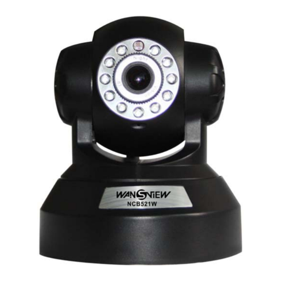
Page 6: Appearance And Interface
2 Appearance and interface Figure 3 521 Device Outlook ①---Wifi antenna;②--- Photoresistor;③---Lens;④—- Holder;⑤—-- IR LED; ⑥--- Microphone;⑦---Base; Figure 4 Connect port ①----Audio Output ②----RJ45 Port ③----Web status LED ④----Web power LED ⑤---WIFI Port ⑥---Power Port... -
Page 7: Visit Ip Camera From Lan
RESET Button: Located in bottom cover, press it and hold on 10 seconds, the device restores factory default and reboot. 3 Visit IP Camera from LAN 3.1 LAN Connection Figure 5 Multiple connected to the router 3.2 Search and set the IP address of IP camera... -
Page 8: Visit Ip Camera
Figure 6 network settings interface diagram Operation Steps: Click “Search (F3) Choose the device On” IP Config” area, make sure IP address – Subnet Mask – Gateway – DNS, the same as the” Local PC Information” – only the red circle is different. -
Page 9: Video Playing Area
Figure 8 Video viewing screen Figure 9 The player controls download prompt box After installation Controller, refresh to view. 3.3.1 Video playing area After install the player controls, click on the figure 10 "Live video ", you can enter the... - Page 10 Figure 10 Video viewing Main menu Main menu includes different sub menu settings, can be hidden and expansion. Status bar Figure 11 status bar ① Record button: click the button, the screen displays rapidly "start record" in the lower right corner, and record icon becomes red, indicates the device is recording, click it again, stop recording;...
- Page 11 Figure 12 Video control 1) Windows: the user can add multiple external devices, and display in multiple window; 2) Resolution: to adjust resolution in the current screen, generally VGA/QVGA optional; 3) Frame rate: to adjust refresh image times per a second;...
-
Page 12: Visit Ip Camera From Wan
14) Start Record/view record: record same as record button in status bar; to view record, it will be open the record file; 15) Start Talk:click the button, transmit audio collecting on your computer into camera, and the camera can play audio via external speaker box, click it again, turn off this feature;... -
Page 13: Ddns
4 which set by you own). Figure 14 Router settings interface After the port-forwarding is done, you could view the IP Camera from WAN using the WAN IP now. Note: Different router has different settings for port-forwarding; please kindly follow your router guide to do the port-forwarding. -
Page 14: Third Party Ddns
DDNS. 4.3.2 Third Party DDNS User can also use third part DDNS, such as www.3322.org User must apply a free domain name from this website and fill the info into the below blanks (Figure 16) and save the settings. Then the domain name can be used. -
Page 15: Wifi Setting
Figure 17 Basic network 5.1.2 WIFI Setting WIFI setting page, as shown in Figure 18, the wireless network list will be listed in search of wireless networks. Select one of the network, and then check "Enable" in the list below the relevant parameters of the selected wireless network will be filled out automatically, enter the key then click Save to complete the wireless network setting. -
Page 16: Upnp Setting
5.1.3 UPnP Setting If you enable UPNP, once the IP camera is connected into the LAN, it will communicate with the router in the LAN to do the port-forwarding automatically. Below Figure 19, tick “Using UPNP to Map Port” and the setting are completed. It will show the setting is successful or not. -
Page 17: Alarm Settings
User needs to apply for a MSN account for this device first, for example: test1@hotmail.com. Please put this MSN account and its password as above Figure 15. Then put your MSN account, for example: friend1@hotmail.com, into the ‘MSN Friends List. -
Page 18: Mail Service Setting
5.2.2 Mail Service Setting Figure 22 example of mail settings The device will send alarm email to you. You only need to fill out the blanks with your email address as shown in Figure 22. After the setting, please click save and test to check if it works properly. -
Page 19: Advanced
Advanced 5.3.1 Device Information Users can view the current device software version, web version, running time, equipment time. Figure 24 Device Information 5.3.2 Device name The user can name the device by himself according to needs。 Figure 25 Device name 5.3.3 User account... -
Page 20: Change Password
5.3.4 Change Password The user can change their password. Figure 28 change password 5.3.5 Date and Time If the device is connected to the Internet, you enable the NTP server to correct the time and select the right time zone. Or you should use the PC’s time to correct its time. -
Page 21: Ptz Setting
Figure 31 create outer device After adding the device, you can make change. Simply click on the "Edit" button to make change as the figure below, the device can also be deleted. Figure 32 edit outer device 5.3.7 PTZ Setting You can choose vertical or horizontal;you can also set the Preset, PTZ speed and the... -
Page 22: Ptz Preset
Figure 33 PTZ setting 5.3.8 PTZ Preset It supports 16 Presets. Please click "re-positioning of pre-position" first, then cruise it to the position you want, and then name this position, finally click “save”. Figure 34 preset settings 5.3.9 Local Setting In this interface, users can do the settings for Taking Pictures, recorded video path, and MJPEG frame rate, to enable alarm recording and alarm time, etc. -
Page 23: Update Webpages
Figure 36 update software 5.3.11 Update WebPages Figure 37 update webpage 5.3.12 Reboot Device Click Restart Now, the pop-up dialog box asks you to confirm that you want to do this, confirmed, restart the device, according to the user's own needs automatically reboot time in minutes hours based (choices are 1,2,3, 4,5 minutes 10,20,30,40,50 minutes, 1 ~ 24 hours). -
Page 24: Log
Figure 39 device setting 5.3.14 Log After enter the log interface, you could view who and when the device is visited. Figure 40 log view Logout:logout ip camera,and then return login interface. 6 IPCMonitor Introduction IPCMonitor is a free software offered by factory, several devices on LAN and WAN can be browsed at the same time. -
Page 25: Faq
Figure 41 ipcmonitor interface For more information, pls. refer to the <<IPCMonitor User Manual>> in CD. 7 FAQ 1. Unmatched power adapter will damage the equipment or power adapter When plug in the power adapter, please check carefully the voltage, it should be 5V adapter for this equipment. - Page 26 4. Can’t find equipment via search software after connect to LAN Make sure the equipment and PC is in the same LAN; if install firewall software, please close it and try again.
Need help?
Do you have a question about the NCB521W and is the answer not in the manual?
Questions and answers