Table of Contents
Advertisement
Quick Links
Operating Instructions and Parts Manual
SPECIFICATIONS
POWER SUPPLY REQUIREMENTS
MOTOR
HORSEPOWER
CUT IN PRESSURE
CUT OUT PRESSURE
PERFORMANCE GAL/HR
Model
PSI
0 ft
30
711
SWS50
40
543
50
375
© 2020, WAYNE/Scott Fetzer Company.
Please read and save these instructions. Read carefully before attempting to assemble, install,
operate or maintain the product described. Protect yourself and others by observing all safety
information. Failure to comply with instructions could result in personal injury and/or property
damage! Retain instructions for future reference.
120 or 230 V, 60 Hz
Single Phase AC Induction
1/2 HP ...................(SWS50)
30 PSI
50 PSI
Well Depth
5 ft
10 ft
15 ft
20 ft
25 ft
674
638
601
565
529
506
470
433
397
361
338
302
265
229
193
Intended for Indoor Use Only
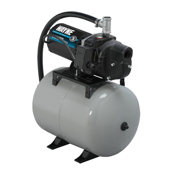
Shallow Well Jet Pump System
CONSTRUCTION
MOTOR HOUSE
Carbon Steel
SEAL PLATE
Cast Iron
DIFFUSER
Thermoplastic
IMPELLER
Thermoplastic
SHAFT
Stainless Steel
PUMP SUCTION
1-1/4 in. NPT
PUMP DISCHARGE
1 in. NPT
www.waynepumps.com
+ Pre-Charged Tank
SWS50-8.5FX
670005W-001 F 07/20
Advertisement
Table of Contents

Related Manuals for Wayne SWS50-8.5FX


Summary of Contents for Wayne SWS50-8.5FX
- Page 1 CUT OUT PRESSURE 50 PSI PUMP DISCHARGE 1 in. NPT PERFORMANCE GAL/HR Well Depth Model 0 ft 5 ft 10 ft 15 ft 20 ft 25 ft SWS50 Intended for Indoor Use Only © 2020, WAYNE/Scott Fetzer Company. www.waynepumps.com 670005W-001 F 07/20...
-
Page 2: General Safety Information
Operating Instructions and Parts Manual DESCRIPTION GENERAL SAFETY INFORMATION Shallow well jet pumps are single stage residential water pumps designed for pumping potable water in applications where the water is located less than 25 feet vertically from the pump. A pressure switch is a standard feature. - Page 3 Operating Instructions and Parts Manual SWS50-8.5FX GENERAL SAFETY INFORMATION (CONT'D) Do NOT touch an operating motor. Modern motors are designed to operate at high temperatures. Disconnect power and release all pressure from the system before attempting to install, service, relocate or perform any Do NOT touch an operating motor.
- Page 4 Operating Instructions and Parts Manual MOTOR END NOTE: Remove pump from stabilizing mount, HEX NUT used for shipping and packing. With motor end of pump facing the “outlet / inlet” end of the tank, mount pump to tank with the provided carriage bolts, nuts and washers as shown (right).
- Page 5 Operating Instructions and Parts Manual SWS50-8.5FX Screw pipe tee onto pipe nipple. Hand tighten. All connections will be fully tightened in steps 7 & 8. Remove protective cover from tank’s outlet/ HOSE-BARB inlet, then screw hose-barb elbow onto ELBOW tank.
- Page 6 Operating Instructions and Parts Manual NOTE: Lubricate the hose-barb and the inside of the hose with clean water or a small amount of liquid dish soap as needed. Slip the hose clamps over the ends of the hose. Attach the hose (with clamps) to the hose-barb using a twisting motion on the hose while pushing it over the hose-barb.
-
Page 7: Pre-Installation
Operating Instructions and Parts Manual SWS50-8.5FX PRE-INSTALLATION Flexible pipe is prohibited on suction pipe WATER STORAGE (inlet pipe). Tanks are required for these pumps to operate as designed. MISE EN GARDE Un tuyau flexible est interdit sur le tuyau TANKS - CONVENTIONAL STORAGE d'aspiration (tuyau d'entrée). - Page 8 Operating Instructions and Parts Manual DUG WELL, CISTERN, LAKE AND SPRING INSTALLATION (FIGURE 12 ON PAGE 14) The foot valve MUST be at least 18” from the 1. Install a foot valve on inlet pipe and lower into water. bottom of the well or sand or sediment WILL be drawn into the system. MISE EN GARDE Le clapet de pied DOIT au moins être The foot valve MUST be at least 18”...
-
Page 9: Operation
Operating Instructions and Parts Manual SWS50-8.5FX ELECTRICAL Disconnect power and release all pressure from the system before attempting to install, service, relocate or perform any Risk of electrical shock. This pump is designed maintenance. for indoor installation unless housed and protected from the elements. -
Page 10: Maintenance
Operating Instructions and Parts Manual MAINTENANCE OUTLET Disconnect power and release all pressure from AIR VOLUME the system before attempting to install, service, relocate or perform any AIR VOLUME maintenance. Lock the power disconnect in the open (OFF) position. Tag HOSE COUPLING out the power disconnect to prevent unexpected application of power. - Page 11 Operating Instructions and Parts Manual SWS50-8.5FX 8. Remove the seal plate. 9. Pry the rotating shaft seal member (including stainless collar SEAL PLATE IMPELLER and rubber seal) from the impeller (Figure 9). ROTATING SHAFT 10. Push or pry the ceramic seat, and rubber seat ring free from SEAL MEMBER the seal plate (Figure 9).
- Page 12 Please provide following information: Address any correspondence to: - Model number WAYNE Pumps 101 Production Drive - Serial number (if any) Harrison, OH 45030 U.S.A. - Part description and number as shown in parts list 1, 2, 3 Ref.
-
Page 13: Troubleshooting Chart
Operating Instructions and Parts Manual Operating Instructions and Parts Manual SWS50-8.5FX TROUBLESHOOTING CHART Symptoms Possible Cause(s) Suggested Remedies Pump will not 1. Power off 1. Turn power on or call power company start or run 2. Blown fuse or tripped breaker 2. - Page 14 Operating Instructions and Parts Manual Operating Instructions and Parts Manual www.waynepumps.com...
- Page 15 LIMITED WARRANTY For three years for SWS50-8.5FX Series models from the date of purchase, from an authorized dealer, Wayne Water Systems will repair or replace, at its option for the original purchaser, any part or parts of its Well Pumps or Water Pumps (“Product”) found upon examination by Wayne Water Systems to be defective in materials or workmanship.
Need help?
Do you have a question about the SWS50-8.5FX and is the answer not in the manual?
Questions and answers