Table of Contents
Advertisement
Quick Links
EVAL-ADCM / EVAL-ADCM-1 User Guide
Date: Jan 18, 2020
ADcmXL Evaluation Wiki link:
https://wiki.analog.com/resources/eval/user-guides/inertial-mems/imu/adcmxl-pc-eval
Contents
EVAL-ADCM / EVAL-ADCM-1 User Guide ............................................................................................ 1
Orderable Part Numbers ....................................................................................................................... 1
Minimum PC System Requirements ................................................................................................... 2
Minimum Required Hardware ............................................................................................................... 2
EVAL-ADCM Hardware Setup ............................................................................................................. 3
Software Installation ............................................................................................................................... 5
Troubleshooting .................................................................................................................................. 6
Verifying the USB Connection .......................................................................................................... 6
Application Functional Overview and User Guide ............................................................................. 6
Devices ................................................................................................................................................ 6
Register Access .................................................................................................................................. 7
Alarms .................................................................................................................................................. 8
Data Capture ..................................................................................................................................... 10
View .................................................................................................................................................... 11
Comm ................................................................................................................................................. 11
Help .................................................................................................................................................... 11
About .................................................................................................................................................. 11
Mode Selection (AFFT, MFFT, MTC and RT) ............................................................................. 11
Orderable Part Numbers
•
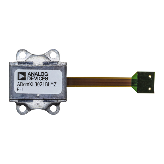
The EVAL-ADCM is an orderable kit that includes ADcmXL3021 module and all necessary
boards to interface with a PC.
•
The EVAL-ADCM-1 is an orderable kit that includes ADcmXL1021-1 module and all
necessary boards to interface with a PC.
1
Advertisement
Table of Contents

Related Manuals for Analog Devices EVAL-ADCM


Summary of Contents for Analog Devices EVAL-ADCM
-
Page 1: Table Of Contents
Mode Selection (AFFT, MFFT, MTC and RT) ................11 Orderable Part Numbers • The EVAL-ADCM is an orderable kit that includes ADcmXL3021 module and all necessary boards to interface with a PC. • The EVAL-ADCM-1 is an orderable kit that includes ADcmXL1021-1 module and all... -
Page 2: Minimum Pc System Requirements
Note: EVAL-ADCM and EVAL-ADCM-1 are identical kits except for included ADcmXL modules. As such, one can evaluate both ADcmXL3021 and ADcmXL1021-1 using EVAL-ADCM (or EVAL- ADCM-1) provided that an ADcmXL1021-1 (or ADcmXL3021) module is ordered separately. Minimum PC System Requirements •... -
Page 3: Eval-Adcm Hardware Setup
Figure 5 Assembled Hardware EVAL-ADCM (or EVAL-ADCM-1) EVAL-ADCM Hardware Setup Figure 6 Hardware included with EVAL-ADCM (or EVAL-ADCM-1) kit. Not shown are 8 mounting screws, short ribbon cable option and an ADcmXL3021 (or ADcmXL1021-1) device. - Page 4 Step 1 Plug in the ADcmXL FX3 Interface Board to the Cypress FX3 Evaluation Board. Figure 7 Pin 3 on both J1 and J2 should be cut. Note: On the ADcmXL FX3 Interface Board, the 2 connectors that interface to FX3 board must have Pin 3 on both headers cut.
-
Page 5: Software Installation
Step 3 Connect either available ribbon cables (short or long) from J5 of the ADcmXL FX3 Interface Board to the pre-assembled ADcmXL3021 (or ADcmXL1021-1) and the ADCMXL_BRKOUT/PCBZ. Note 1: The shorter ribbon cable (2”) is required for RTS Mode but may be used in any of the operation mode. -
Page 6: Troubleshooting
Universal Serial Bus controllers as “Cypress FX3 USB BootLaoder Device”. This is confirmation that the Cypress USB drivers have been installed. When the ADcmXL Evaluation Software application is started the device should reconnect as an “Analog Devices iSensor FX3 Demonstration Platform”. -
Page 7: Register Access
Register Access Provides an interface for reading and writing the registers of the device. The left side panel shows Registers grouped into Categories: Control/Status, Output, Calibration and Filter Bank. The panel on the right displays the bit fields of a selected control register selected from the pull down menu at the top. -
Page 8: Alarms
4. To read register values from a file and load the values to the ADCMXL. Press the Read button in the Register Access Form. Use the file open dialog to select a properly formatted RegDump.csv file. Press Open. The values will be written to the registers of the ADCMXL device. - Page 9 Setting Alarms and Reading Alarm Status Reading Default Values 1. Open Alarm Values Window by selecting “Alarm” on the top bar of the Evaluation Software window and then “Alarm Values”, which will open a window. 2. Readback the current register values by pressing the “Read Default Values”. Reading from current active values and writing values in table to DUT 1.
-
Page 10: Data Capture
Figure 14 Alarm band lines and Alarm Status form (overlay) shown in an example vibration measurement. X-axis alarm is disabled. Data Capture The user can configure where the files to be stored and reset the file count. To set the Data Capture options, open the Data Capture Configuration dialog window by selecting “Data Capture”... -
Page 11: View
View Provides an optional control to display any combination of the available axes (only in case of ADcmXL3021). Note about plot setting • Right Click any plot to display the scaling controls. • Scaled coordinates of the cursor are displayed at the bottom of each plot. •... - Page 12 5. On the left panel, use the slider to find the Register called REC_PRD. Use the pointer to select this register after which the register name will appear in the top center of the Register access window. Enter “2” in the New Hex Value entry and push the “Write” button. This configures the device for an automatic repeat time of 2 seconds.
- Page 13 4. Press “Write” next to the Auto-Null under the listed Functions which should be shown on the top of the right panel. This will initiate a DC offset null calculation and will take less than 1 seconds. 5. Return to the Main ADCMXL Evaluation Software window and press “Start”; a new Manual Time Capture will initiate and complete within a few seconds.
Need help?
Do you have a question about the EVAL-ADCM and is the answer not in the manual?
Questions and answers