Advertisement
XMP 240 C AT • Setup Guide
This guide provides basic instructions for an experienced technician to install the XMP 240 C AT Expansion Matrix Processor. For
more information, specifications, and the user guide, see the XMP 240 C AT product page at www.extron.com.
Disconnect Power and Mount the XMP 240 C AT
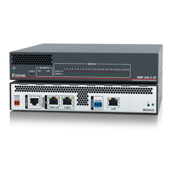
Disconnect power from the XMP 240 C AT and turn off all devices that will be connected to it. The XMP 240 C AT is housed in a
half rack width, 9.5 inch deep, 1U high metal enclosure that can be rack mounted or placed on a table with the provided rubber
feet. Select a suitable mounting location, then choose an appropriate mounting option. Mounting information can be found in the
XMP 240 C AT User Guide on www.extron.com.
Make all external device connections before applying power.
Rear Panel Connections
POWER
12V
1.0A MAX
1 (PRI) PoE
A
B
C
Figure 1.
XMP 240 C AT Rear Panel
AC Power — Connect the provided 12 VDC power supply to the rear panel 2-pole captive screw connectors (see the XMP
A
240 C AT User Guide for wiring instructions).
DMP EXP Port — Connect an EXP-enabled device to this RJ-45 port for a digital audio connection using Extron proprietary
B
protocol. Use the included one foot long shielded CAT 6 cable to connect two EXP-enabled devices to form a larger matrix
system. The expansion bus supports 16 bidirectional channels of audio (see the XMP 240 C AT User Guide for EXP bus
operation details).
AT Ports — Two RJ-45 ports form a Gigabit switch that interfaces with the AT bus. The AT expansion bus uses Dante
C
protocol for digital audio networking and allows XMP 240 C AT models to connect with other Dante-enabled devices to form
a larger matrix (see the XMP 240 C AT User Guide for operation details).
NOTE:
Dante Controller software is required for configuration. Dante Controller is available at
www.extron.com
REMOTE RS-232 Port — Use a 3.5 mm 3-pole captive screw connector to connect the
D
host RS-232 cable for bidirectional RS-232 (±5V) serial control (wiring shown to the right).
The default baud rate is 38400.
LAN Port — One RJ-45 port is available for control, configuration, and firmware updates.
E
Port
LAN
Reset Button and LED — The reset button returns the XMP 240 C AT to different tiers of default states. When using the reset
F
function, the LED blinks to signify the different reset modes. When not using the reset function, the LED operates as a power
indicator and matches the front panel power LED (see the Reset Modes section of the XMP 240 C AT User Guide for more
information on the different reset modes).
When all connections have been made, power up the input and output devices, then apply power to the XMP 240 C AT.
RS-232
2 (SEC)
Tx Rx G
LAN
E
C
D
(see the following page for download and installation instructions).
Default IP Address
192.168.254.254
R
XMP 240 C AT
F
Default Subnet Mask Default Gateway
255.255.255.0
0.0.0.0
™
Tx
Transmit
Rx
Receive
G
Ground
Default DHCP
OFF
RS-232
Tx Rx G
1
Advertisement
Table of Contents

Subscribe to Our Youtube Channel
Related Manuals for Extron electronics XMP 240 C AT


Summary of Contents for Extron electronics XMP 240 C AT
- Page 1 Disconnect Power and Mount the XMP 240 C AT Disconnect power from the XMP 240 C AT and turn off all devices that will be connected to it. The XMP 240 C AT is housed in a half rack width, 9.5 inch deep, 1U high metal enclosure that can be rack mounted or placed on a table with the provided rubber feet.
- Page 2 XMP 240 C AT Configuration When power is connected to the XMP 240 C AT and the rest of the audio system, audio output can be tailored to any listening environment. When configuration is required, changes are made using DSP Configurator.
- Page 3 Emulate mode and save the configuration file. To push a configuration to the XMP 240 C AT or pull the current configuration from the XMP 240 C AT, enter Live mode. When in Live mode, changes made in DSP Configurator affect the connected XMP 240 C AT immediately. To enter Live mode, click Live at the top of the DSP Configurator workspace, select Tools >...
- Page 4 Regulatory Compliance Guide on the Extron website. www.extron.com © 2020 Extron Electronics — All rights reserved. All trademarks mentioned are the property of their respective owners. 68-3434-50 Rev. A Worldwide Headquarters: Extron USA West, 1025 E. Ball Road, Anaheim, CA 92805, 800.633.9876...
Need help?
Do you have a question about the XMP 240 C AT and is the answer not in the manual?
Questions and answers