Advertisement
SMP 401 • Setup Guide
IMPORTANT NOTE:
Go to
www.extron.com
product to the power source.
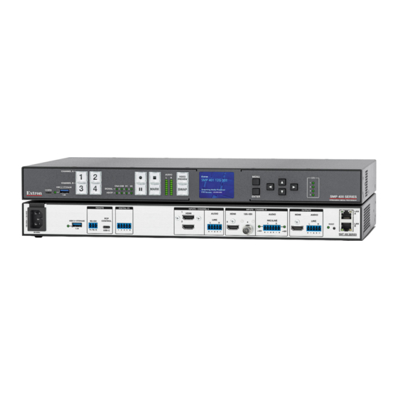
The Extron SMP 401 Streaming Media Processors are high performance all-in-one multi-channel 4K/60 recording and streaming
processors. The SMP 401 accepts HDMI, optional 12G-SDI, line level or mic level audio with phantom power. It can create up to five
independent recordings and simultaneously provide up to six streams, with different encoder settings and separate audio, when using with
two virtual inputs. The SMP 401 is a flexible, robust solution for environments that require multiple high-quality recordings and live streams,
such as lecture capture and HyFlex learning, government and healthcare training, courtrooms, and command and control centers (see
available features at www.extron.com).
Mount the SMP 401
The SMP 401 models are housed in a 1U high, full rack width metal enclosure that can sit on a table with the provided rubber feet or
mounted using the attached rack mounts. Select a suitable mounting location, then choose an appropriate mounting option.
Before connecting the SMP 401, turn off all devices to be connected. Then make all external device connections to the SMP 401 before
applying power to the devices.
Rear Panel Overview
USB 3.1 STORAGE
1.5 A
50-60 Hz
A
A
A
B
B
B
Figure 1.
SMP 401 Rear Panel
100-240 VAC IEC power inlet
A
USB storage device port and LED
B
Remote RS-232 port
C
RCP control port
D
Digital I/O ports
E
Power Connection
100-240 VAC IEC power inlet – Connect the provided IEC cord. Verify the front panel buttons and LCD illuminate (see
A
Features
on page 3).
Control and External Device Connections
The SMP 401 can be configured and controlled from the remote port (see figure 1,
Config port (see figure 5,
Config port or the LAN ports for configuration, remote control, and firmware upgrades.
USB storage device port and LED — Connect a USB compatible media device to this port. The storage device can be any standard
B
external hard drive or USB flash drive formatted with a compatible file system. The LED lights:
•
Green — Record Destination is set to USBRear or Auto and the attached storage device is ready for recording. Also, blinks green
during both reading and writing.
•
Red — Record Destination is set to USBRear and the attached storage device is detected, but recording will not start because
the file is write protected, in an unsupported file format, or there is less than 10 minutes of free recording space.
NOTE: The SMP 401 can detect and record to USB storage devices using exFAT, FAT32, NTFS, VFAT long file name extensions,
EXT2, EXT3, or EXT4 file systems.
for the complete user guide, installation instructions, and specifications before connecting the
REMOTE
DIGITAL I/O
RCP
RS-232
CONTROL
1 2 3
4 G
Tx Rx
G
USB-C
C
C
C
D
D
D
E
E
E
F
G
H
I
J
on page 3) or the LAN ports (
B
INPUTS-CHANNEL A
1
HDMI
AUDIO
LINE
3
2
L
R
F
F
F
G
G
G
HDMI inputs (1 and 2)
Analog audio input
HDMI input 3
(Optional) 12G-SDI input 4
Analog Mic/Line audio input
C
) using a standard web browser. Extron recommends using the USB-C
N
INPUTS-CHANNEL B
HDMI
12G-SDI
AUDIO
HDMI
MIC/LINE
4
1
2
+48V
+48V
H
H
H
I
I
I
J
J
J
K
K
K
HDMI output
K
Analog audio output
L
Reset button and LED
M
RJ-45 Ethernet LAN ports
N
) using SIS commands or the front panel USB-C
OUTPUTS
LAN
A
AUDIO
LINE
LAN
RESET
L
R
B
SMP 400 SERIES
L
L
L
M
M
M
N
N
N
Front Panel
1
Advertisement
Table of Contents

Subscribe to Our Youtube Channel
Related Manuals for Extron electronics SMP 401


Summary of Contents for Extron electronics SMP 401
- Page 1 Mount the SMP 401 The SMP 401 models are housed in a 1U high, full rack width metal enclosure that can sit on a table with the provided rubber feet or mounted using the attached rack mounts. Select a suitable mounting location, then choose an appropriate mounting option.
-
Page 2: Input Connections
Digital I/O ports — This 3.5 mm, 5-pole captive screw port provides four user-defined digital inputs and outputs. Reset button and LED — The SMP 401 has several reset modes to return user-defined configuration settings or all settings back to factory defaults. The LED blinks to indicate the desired reset mode, and provides the reset status during the reset operation (see the SMP 401 User Guide for information on reset modes). -
Page 3: Front Panel Features
10 minutes of free recording space. NOTE: The SMP 401 can detect and record to USB storage devices using exFAT, FAT32, NTFS, VFAT long file name extensions, EXT2, EXT3, or EXT4 file systems. -
Page 4: Main Menu Options
SMP 401 • Setup Guide • MARK — Press to place a chapter marker in the recorded file. When pressed during recording, the green MARK button blinks momentarily to indicate a chapter marker is inserted. Also illuminates when JPG thumbnails are automatically created at 5 minute intervals by default. -
Page 5: Network Configuration
Network Configuration The SMP 401 is pre-configured with the network settings shown in the image below. These menus are part of the Admin menu that require sequential button presses to access. NOTES: • With these settings, the control PC and viewing devices must have an IP address within the 192.168.0.1 through 192.168.254.254 range and have the same subnet. -
Page 6: About The Web-Based User Interface
DOWN arrows to scroll through the selections and press ENTER to activate a selection. About the Web-based User Interface The web-based user interface can view, configure, and control the SMP 401 with a PC from either LAN port or the front panel USB-C port using a standard web browser (see Network Configuration...
Need help?
Do you have a question about the SMP 401 and is the answer not in the manual?
Questions and answers