WM Systems WM-E1S Datasheet And User Manual
Metering modem
Hide thumbs
Also See for WM-E1S:
- Datasheet and user manual (17 pages) ,
- Datasheet and user manual (51 pages)

Related Manuals for WM Systems WM-E1S


Summary of Contents for WM Systems WM-E1S
- Page 1 Datasheet and User manual for WM-E1S metering modem ® ______________________________________________ ____ Rev: 2.73 2022-03-08...
-
Page 2: Document Specifications
Document specifications This documentation was made for presenting the installation and configuration steps of the WM-E 1S energy metering modem. ® Document Version: REV 2.73 WM-E1S ® modem Hardware Type/Version: for the Elster ® / Honeywell ® Alpha A1500, A1700, A1800, A1140/A1160... -
Page 3: Chapter 1. Introduction
Chapter 1. Introduction The WM-E1S is a modem, which is suitable for ® automated remote reading electricity meters remotely, on the 4G LTE-based cellular network. You can save money by using our modem, because furthermore there is no need of manual readout of the meter systems. - Page 4 Design and installation This modem was especially developed for the 3-phase Elster /Honeywell A1500 ® ® Alpha, A1800 Alpha, A1140 Alpha, A1160 Alpha, A1700 Alpha type energy meters, which can be connected to the meter by its design and its connection interface and can be installed into the meter enclosure’s terminal cover.
- Page 5 electricity meter registers. and remote reading of load curves, use of standard reading commands, remote reading and modification of the meter / parameters, updating of the meter application firmware. Over the RS232/RS485 compatible data connection, some models have the 2-Inputs option (for sabotage or relay/tariff switch status).
- Page 6 In case of a power outage, the supercapacitors will discharge by time, and the modem will shut down. When the power supply returns, the modem restarts and sends data over the cellular network, and the capacitor components will be charged). Configuration and firmware refresh The modem can be configured locally via RS232 port, remotely with a CSData call (only if you use a setting that also uses a 2G network!) Or via a mobile internet (TCP)
- Page 7 Expansion: 2-inputs board The metering modem in case of need, can be ordered with a 2-inputs expansion board (with 4-pins wire and sleeve connection). The input can be used with sabotage detection and for status alarm signaling (receiving the current status of the inputs). Status and notification The modem is continuously monitoring the mobile network and device communication health, and can send status information (signal strength, QoS).
-
Page 8: Chapter 2. Connectors, Interfaces
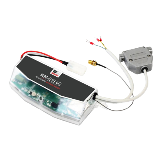
Chapter 2. Connectors, interfaces 2.1 Modem with RS232/RS485 connector (for Honeywell ® , Elster ® meters) 1 – Mains connector (pigtail connector, for the AC power of the meter) 2a – RS232 connector (DSUB9 - optional) 2b – RS485 connector (2-pin or 4-pin - order option, wire with sleeve) 3 –... - Page 9 2.2 Modem with RS232 connector and 2-Input add-on 1 – Mains connector (pigtail connector for the AC power of the meter) 2a – RS232 connector (DSUB9 - optional) 3 – Antenna connector (SMA-M, 50 Ohm) 4 – SIM card slot (push-insert) 5 –...
- Page 10 2.3 Modem with RS485 connector and 2-Input add-on 1 – Mains connector (pigtail connector for the AC power of the meter) 2b – RS485 connector (2- or 4 pin wire with sleeve – order option) 3 – Antenna connector (SMA-M, 50 Ohm) 4 –...
- Page 11 2.4 Modem with RJ12 connector (RS232) 1 – Mains connector (100V AC - to the meter) 2 – RS232 connector (RJ12 – data connection modem → meter) 3 – External antenna connector (SMA-M, 50Ω) 4 – SIM card slot (mini SIM, insert-push) 5 –...
- Page 12 2.6 Modem RJ12 with connection (RS485) for Honeywell and other ® type meters 1 – Mains connector connector (pigtail connector for the AC power of the meter) 2 – RS485 connector (RJ12 – for data connection modem → meter) 3 – External antenna connector (SMA-M, 50Ω) 4 –...
- Page 13 2.7 Universal metering modem with external mounting (with RJ12 connector and DIN-rail adapter mounting) 1 – Mains connector connector (pigtail connector for the AC power of the meter) 2 – RS232 (gray) or RS485 (black) connector (RJ12 data connection modem → meter and for the configuration of the modem) 3 –...
-
Page 14: Installation Steps
2.8 Installation steps Step #1: Remove the meter terminal cover (I), loosen the screws (J). Step #2: Ensure that the device is not powered on, remove the AC connector (1). Step #3: Insert a replaceable and active SIM card (with APN) into the SIM-holder (4) - the chip looks down, and the cutted edge of the SIM looks to the modem. - Page 15 Step #9: After completing the configuration, remove the R232 cable (or RJ12 cable) - labeled 2/2a - from the USB adapter. Step #10: Disconnect the modem AC power connector (1) from the meter (or power source). The modem will be shutting down. Step #11: Make a data connection between the modem and the meter on the interface you want to use (port nr.
- Page 16 2.9 Connecting the modem to the meter (Elster / HON Alpha meters) ® ® Step #1: Remove the Elster A1500 and A1700 Alpha meter’s communication module ® plastic case by releasing the 2 screws from the top of the housing. Step #2: Connect to the meter using the data connector.
- Page 17 Step #3: Connect the modem's plastic power plug (1) to the meter's two-wire connection (marked “E” in the following figure). If the AC power connector is not a power plug but a wire end ferrule, connect the wires to the meter phase and ground.
- Page 18 Step #4: If you haven’t already done, connect the appropriate antenna (3) to the modem swing connector. Step #5: Connect the wire end sockets of the modem AC cable (1) to the meter, to the AC power connection points (red and black wire) - carefully, because during this, the meter can be under 100-240V AC supply voltage! Since now, the modem gets its power from the meter.
- Page 20 If you want to connect RS232 (labeled 2 or 2a), connect it to the RS232 socket marked “G” on the meter. Wiring to the Elster /Honeywell Alpha A1800 meter ® ®...
- Page 21 In case of using RS232 connection only – as you can see in the next photo – you don’t need the RS485 4-wire connection – signed with C – but you have to use the RS232 connection of the modem – signed with G – to connect it to the right data RS232 serial connection position –...
- Page 22 In case of using the RS485 and the RS232 serial connection together – as you can see in the next photo – you have to apply all described connection ways to the proper data connection (the RS485 4-wire connection (signed with A) and the RS232 serial data connector (H + G) then the power supply connection (signed with C).
-
Page 23: Antenna Connection
2.10 Antenna connection The modem requires enough signal strength of the cellular network and LTE or similar antenna for the proper operation and good communication. Where the signal strength of the cellular network is sufficienty, there an internal antenna may be enough to use. However, in places where the signal strength is low or poor, you should use an external antenna (50 Ohm, SMA connector), which can be mounted to the modem –... - Page 24 Factory default LED signals: LED identifier Events LED 1 • If there is a SIM and PIN code ok, the LED will turn on • If there is no SIM or the SIM PIN is incorrect, the LED GSM / GPRS status flashes every 1 second.
- Page 25 Further status LED signals (can be configured as well): LED identifier Events E-meter relay status - E- • Default status: “Ready” - LED flashes 1x per second • “Active” mode - the *relay switched, which turns on the meter relay* output status LED when it is switched on.
- Page 26 During firmware upload, the LEDs indicate normal operation - there is no distinct indication during the FW update. After installing the FW, the three LEDs light up for 5 seconds and then all three light up. The modem will then restart and use the new firmware.
-
Page 27: Rs485 Connector Pinout
There is opportunity to monitoring – as a safety option – sabotage events or detect the relay/tariff change or relay switching changes. Therefore the device is able to detect the input signal changes and generating and transmitting SMS alert notification – according the settings. - Page 28 2.15 Push operation method The complete readout and data sending mechanism to the centre and the other direction for the configuration and maintenance tasks can be realized on the defined paths. The modem does not operate continously on the network. Therefore, there is an another option and meter data sending mode to initiate a remote readout automatically in the pre-defined intervals.
- Page 29 • The readings shown as standard IEC format, including some ASCII control characters like STX ETX, etc. also. - Alarm Push (sending alarms) - starting when new event can be read from meter • Alarm Push method triggers TCP sending of a DLMS WPDU contains the IP address, •...
- Page 30 PDP connection delay field in the APN parameter group. For more information, see Chapter 3.1 of the WM-E Term User Manual. 2.18 Data control direction (DCD) feature In case of using the WM-E1S modem with Itrón SL7000 or other meters or the WM- ®...
- Page 31 Important! This feature needs of using the 2.49B or later firmware version for the modem. 2.19 Automatic network reconnection If the mobile network provider drops the modem from the cellular network due to the device’s network inactivity, there are available parameters if these are set, then automatic and periodical connection connection rebuild can be caused.
- Page 32 If you set this parameter to a low value that can cause frequent network reconnections. Therefore under no circumstances should you set this value lower than what your mobile service provider recommends. (e.g. there are mobile network providers that limit the number of times a modem can log on to the network in a given time).
-
Page 33: Chapter 3. Modem Configuration
Chapter 3. Modem Configuration 3.1 Configuration The modem must be configured by the WM-E Term software by configuring its ® parameters which must be performed before the normal operation and usage. Over the parameter settings of meter, modem and communication, etc., you can also test the modem communication by the configuration program. - Page 34 In places where the signal strength is strong it is possible to use internal antenna, for areas with poor reception mount an external antenna (50 Ohm SMA connection) to the antenna connector (3) of the device, which you can place inside even inside the meter enclosure (under the plastic housing).
- Page 35 Factory configuration file sample (for WM-E Term): https://www.m2mserver.com/m2m-downloads/WM-E1S_STD_default.zip For the operation of the modem cellular network communication and SIM card settings (such as APN, password, and account) are required. In addition, be sure to review and save the transparent mode data speed functions in the WM-E Term program for the RS232, RS485 settings.
-
Page 36: Chapter 4. Support
The product has a identification void which has important product related information for the support line. Warning! Damaging or removing the void sticker means the loss of product guarantee. Online product support available here: https://www.m2mserver.com/en/support/ 4.2 Product Support The documents and information related on the product are available here. https://www.m2mserver.com/en/product/wm-e1s/... -
Page 37: Chapter 5. Legal Notice
WM Systems LLC. only. The figures in this document are illustrations, those can be different from the real appearance. The WM Systems LLC doesn’t take any responsibility for text inaccuracy in this document. The presented information can be changed without any notice.
Need help?
Do you have a question about the WM-E1S and is the answer not in the manual?
Questions and answers