
Related Manuals for WM Systems WM-I2


Summary of Contents for WM Systems WM-I2
- Page 1 User manual for WM-I2 ® metering modem v1.2 ______________________________________________ 2020-11-16...
-
Page 2: Document Specifications
Document Version: REV 1.2 Hardware Type/Version: WM-I2 ® pulse counter modem Hardware Version: V 2.10 Bootloader Version: V 1.80 Firmware Version: V 2.04.05 WM-I2 Term ® configuration V 0.44 software version: Pages: Status: Final Created: 16-11-2020 Last Modified: 16-11-2020... -
Page 3: Chapter 1. Introduction
Chapter 1. Introduction The WM-I2 ® is a pulse counter modem with LTE Cat.NB data transmission capabilities. It is suitable for receiving and counting the incoming pulse signals of the connected utility meter or sensor (water, gas, electricity or calory meter) data from the meter’s S0 type output. It is transmitting data in the pre-configured intervals through the cellular network to the data center or a server IP address. - Page 4 TCP (after configuring the APN, username and password parameters by the hints of your mobile operator). All data transmission related settings, meter counter handle, measurement units, operation cycles of device wake-up/data storage/data sending can be all configured by the downloadable WM-I2 Term ®...
-
Page 5: Chapter 2. Connections
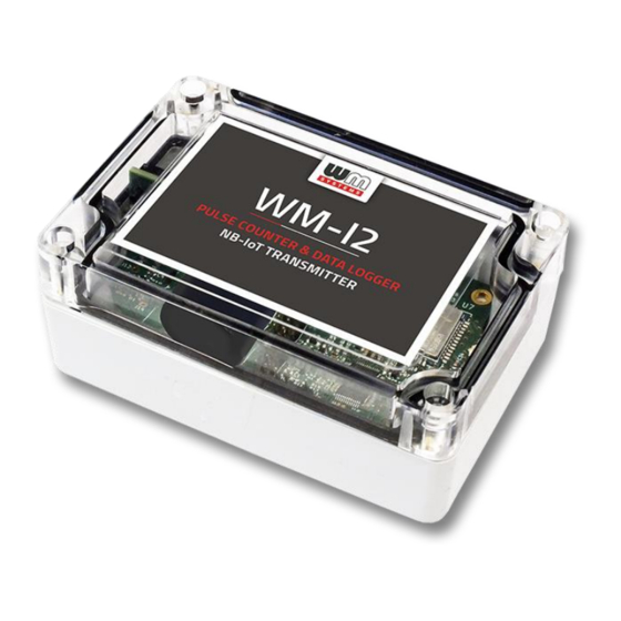
Chapter 2. Connections 2.1 External view 2.2 External view (bottom side) The top cover of the modem’s enclosure, which provides a safe and dehumified lock by using the internal silicone ring inside of the cover. - Page 6 2.3 Internal connectors, interfaces LEDS – – – 1 – Enclosure bottom part (ABS plastic with IP67 protection and 6 holes – where the PCB can be fastened into the enclosure by screws at holes) 2 – Enclosure top part (sealable, can be fastened by 4 screws) 3 –...
- Page 7 2.4 Fixation of the enclosure The enclosure can be fastened and fixed by screws (at point nr. 14) or a metal strip (at point nr. 15) and mount to wall or the pipeline. 2.5 J11 connector pinout Connection interface with cabling (terminal block, J11) which can be used: –...
-
Page 8: Installation Steps
Not used Digital INPUT GND for INPUT INPUT – for detecting cut of the cable branch 2.6 Installation steps Step #1: Remove the enclosure’s plastic top cover (2) by releasing and removing the four screws (3) by a screwdriver. Step #2: Remove the jumper from the DC battery connector (9) and the device will be stopped. - Page 9 : The opposite side of the USB configuration cable must be connected to the J11 connector’s terminal block (nr. 8 on the figure) pins of WM-I2’s mainboard (nr. 14). The wires must be plugged according to the next wiring and the figure: –...
- Page 10 (check the Chapter 2.3). Pulse input is the pin nr. 8, etc. Step #11 : Configure the parameters of operation by usage of the WM-I2 Term software. Step #12: After the successful configuration disconnect the USB adapter (11) from your computer...
- Page 11 Step #13: Ensure that the internal antenna UF.L connector (4) is connected to the mainboard. Step #14: Mount an LTE antenna to the external antenna connector on the device. Step #15: Install the modem enclosure (1) by the bottom-side and fasten / mount to wall – near to the meter –...
-
Page 12: Chapter 3. Modem Configuration
Chapter 3. Modem Configuration 3.1 Settings The modem must be configured by the WM-I2 Term ® software by configuring its parameters which must be performed before the normal operation and usage. Important! The modem is operating during most of the time in stand-by mode. It is continously receiving the incoming pulse signals and counting them. - Page 13 #Step 3. You have to own administrator privileges for the directory where you are using the program. #Step 4 . Download the WM-I2 TERM ® tool to your computer by using this link from a web browser: https://www.m2mserver.com/m2m-downloads/WM-I2Term_v0_4_4.zip #Step 5.
- Page 14 #Step 3: Add the IMEI identifier (15 or 17 characters long) into the popup window. #Step 4: Define a modem name (logical identifier – free to choose) for the better device identification. Use for onsite installation place, unique name of identification, etc. #Step 5: Then the new device entry will appear in the list of the devices.
- Page 15 The meaning of the following buttons: Load list: load a previously saved device list (if you copy the list file to an another computer, you can clone more devices in one step). Save list: you can save the list to your computer Add new: add a new device to the list Add mass: you can add more devices in one step (device list must be in .TXT extension text format)
-
Page 16: Required Settings
Then the following window appears, where you can setup the compatiblity by selection buttons as MBUS Pulse Meter type ( ) / Data sending method: #Step 7: By selection of the listed tabs you can modify the parameter groups here: Validity Communication settings: cellular network settings, selection of APN, server port and IP address... - Page 17 Server IP address: where you would like to send the data Server Port number Destination server protocol: GRF (Grafana server), FTP, MQTT, CoAP, LwM2M (Lightweight M2M)) Configuration server IP address: a remote location, where the modem will searching and downloading the valid configuration Configuration port Cellular network country code, network code: choose the SIM provider from the list...
- Page 18 #Step 3: Setup the minimum required fields on the Extended configuration tab and below at the Life signal and Time server settings tab: Life signal sending IP address: where you want to signalling the life signals of the devices...
- Page 19 Life signal sending port Life signal sending protocol: time server communication format, which can be: MQTT, STNP, NTP, LwM2M Time server IP address: where you want to getting the date and time (imortant for reliablity and validation of data) Time server port Starting LED operation time: you can define the LED operation duration, which means how long will be active the LED, when you connect the battery or pushing the tamper switch (at enclosure top cover’s close).
- Page 20 #Step 5: Setup the minimum required fields on the Extended configuration tab and below at the Schedule tab: Delta pulse sending (input #1): megadható, hogy a megadott impulzusszám növekedés esetén automatikusan, soron kívüli adatküldés történjen – nem kötelező beállítani (ez esetben hagyja 0-n az értéket) Data sending interval: define the data sending cycle (in seconds) Data storage frequency: define the data storage in memory cycle #Step 6:...
- Page 21 3.6 Sending the parameters to the modem After making the settings, choose the Save button for savig the current configuration to JSON or XML, cbor file to your computer. If you want to send the configuration to the modem, choose the Assign to IMEI button. At the next connection (in case of using the Connection settings / Communication / SETTINGS ...
- Page 22 3.7 Connection settings – IF the modem was already configured #Step 1: Push the icon on the main window, and select a connection mode: - Listener IP address connection, if you want to configure the device by remote TCP Listener connection (in this case you have to know the SIM card’s registered IP address ( IP address Listener port...
- Page 23 Waiting for data… When the access if possible, the message will appear at the State. Then the WM-I2 Term program will readiout the IMEI identifier of the modem and the device configuration will be ready to download by the button.
-
Page 24: Event Log
3.8 Event log The incoming events and software messages are recorded into the log. The log entries can be seen by pushing the icon and choosing the Event Log tab. The list can be orderd and saved into various formats here by the buttons. 3.9 Refresh modem firmware #Step 1: Choose the... - Page 25 #Step 2: Chose the Firmware tab and the Choose Firmware button, and browse the firmware file you want to upload to the modem (with *.dwl extension).
-
Page 26: Program Settings
#Step 2: Push the Save the directory (path) of the firmware for a later update button. The firmware update request is already configured. At the next connection (Connection settings / Connection / SETTINGS Sending data) the new firmware will be sended to the modem.
Need help?
Do you have a question about the WM-I2 and is the answer not in the manual?
Questions and answers