
Related Manuals for WM Systems WM-E2S


Summary of Contents for WM Systems WM-E2S
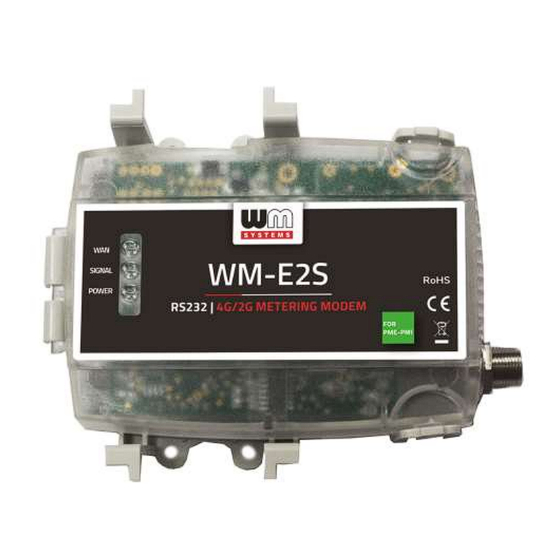
- Page 1 Datasheet and User manual for the WM-E2S 4G modem ® to the PME-PMI ® electicity meters ______________________________________________ Rev: 2.51 2020-04-01...
-
Page 2: Document Specifications
Document specifications This documentation was made to present the installation and configuration steps of the WM-E2S 4G ® electricity metering modem for PME-PMI ® electricity meters. Document Version: REV 2.51 WM-E2S 4G ® modem Hardware Type/Version: for electricity metering with DC power supply for the PME-PMI ®... -
Page 3: Chapter 1. Introduction
Chapter 1. Introduction The WM-E2S 4G ® is a modem, which is suitable for automated remote reading of electricity meters, on the 4G LTE-based cellular network. You can save money by using our modem, because there is no further need of manual readout of the meter systems. - Page 4 Power source and power outage The device is powered by DC power internally by the meter’s RJ45 connection. The device is equipped with an internal supercapacitor, which overbridges the intermittent power cuts and also helps decrease power peaks. Configuration The modem is configurable via TCP/UDP port remotely (or via local serial connection) and operates on the wireless network by configuring the APN, username and password (APN information is provided by your local mobile operator).
- Page 5 Certification The modem conforms to the CE standard and the Radio Equipment Directive (2014/53/EU), safety directives (EN 60950-1).
-
Page 6: Chapter 2. Connections
Chapter 2. Connections 2.1 External outfit 1 – Plastic transparent top cover 2 – DIN-rail adapter (to mount) 3 – Alternative fixation lugs/holes 4 – Cover holders (loosen them to let cover open up) 5 – FME antenna connector (50 Ohm) 6 –... -
Page 7: Installation Steps
2.3 Installation steps Step #1: Ensure that the device is not powered on, remove the RJ45 connector (10). Step #2: The modem is provided with an anodized aluminum DIN-rail adapter for 35mm DIN rails (2). The fixation part can be found on the bottom side of the modem enclosure. - Page 8 Step #6 : Insert a replaceable and active SIM card (with APN access) into the SIM-holder (8) - the chip looks down, the cut edge of the SIM is oriented towards the antenna side Step #7 : Close down the SIM holder (8) and push it from right to left until it is fastened, and close back the PCB- side of the enclosure (semi-transparent...
- Page 9 Step #10: Close the plastic cover (1) of the product case and install the modem by fixing the enclosure onto the 35mm DIN-rail. Step #11: Mount a 4G antenna (you can use an FME-type by the FME antenna connector (5) or use SMA-type by an FME-to-SMA converter).
- Page 10 2.5 Status LED signals If the WM-E2S 4G ® modem has not been connected to a power source for a long time, it needs to be charged before usage/installation. The complete charge process takes about ~2-5 minutes if the super-capacitor parts are exhausted / discharged previously.
- Page 11 LED 11 Lighting continuously, while the modem is not registered on the network and while no RSS response (SIM is ok) SIM status / SIM or PIN When the SIM PIN is okay: led is active failure If no SIM can be detected or the SIM PIN is wrong: blinking once per second (slow flashing)
- Page 12 During the firmware uploading the LEDs are opeating as it is normal – there is no significal LED signal for the FW refresh progress. After the Firmware installation, the 3 LEDS will be lighting for 5 seconds and all will blank, then the modem restarting by the new firmware. Then all LED signals will be used as it was listed here above.
- Page 13 In case of recovering the mains/power source the modem generates the “POWER RETURN” message and sends it by SMS text. The LastGASP message settings can be enabled by the WM-E Term ® application – in the AMM (IEC) parameter group part.
-
Page 14: Chapter 3. Modem Configuration
Chapter 3. Modem Configuration 3.1 Configuration The modem must be configured by the WM-E Term ® software by setting its parameters which must be performed before the normal operation and usage. Over the parameter settings of meter, modem and communication, etc., you can also test the modem communication and execute AT-commands on the modem by the configuration program AT commands - see... - Page 15 Databits: 8 Parity: No Stopbits: 1 Bandwith control: no For the proper communication of the modem, you have to configure the APN settings of the SIM – as PIN code, APN, username and password. These all can be configured by using the WM-E Term ®...
-
Page 16: Signal Strength
WM-ETerm.exe Unzip the .zip file and start the software by the file. You can login into the configuration software by the default password. You can change the User Manual password for the configuration anytime you want. Check the WM-E Term ®... - Page 17 The meter communication requires to define the communication port, the RS232 settings (transparent mode, baudrate, data format, transmitting speed), LEDs settings and to save the User Manual settings by the WM-E Term ® software then upload/send them to the modem by the of the software.
- Page 18 Firmware refresh: choose the Devices menu, Single Firmware refresh item by choosing the appropriate firmware file (with .DWL file extension). Attention! Ask our sales about the available newest firmware!
-
Page 19: Chapter 4. Legend
Chapter 4. Legend GSM (Global System for Mobile Communications) is the most popular standard for mobile telephony systems in the world. GSM is a cellular network, which means that mobile phones connect to it by searching for cells in the immediate vicinity. GPRS General Packet Radio Service (GPRS) provides more efficient packet-based data transmission directly from the mobile phone at speeds similar to HSCSD.
Need help?
Do you have a question about the WM-E2S and is the answer not in the manual?
Questions and answers