Advertisement
Quick Links
*030794*
030794
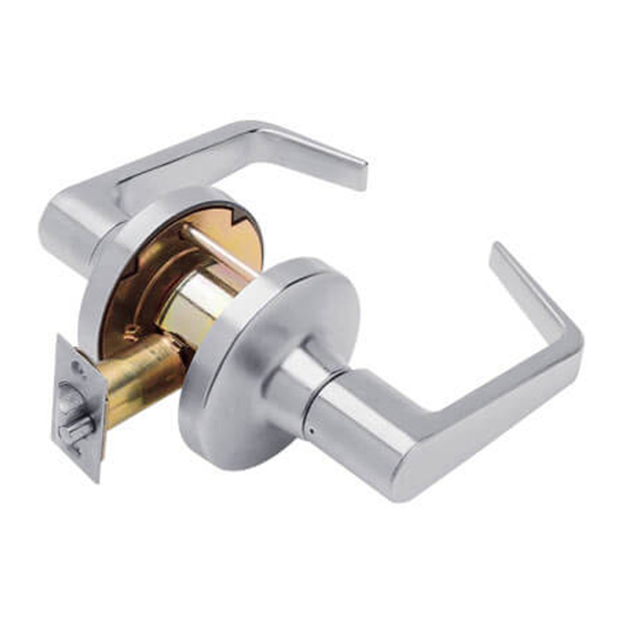
Extra Heavy Duty Lockset
IMPORTANT: This lock is non-handed. Lock is factory packed preadjusted for 1C\v" (45 mm) thick doors. To adjust the lock for other
door thickness, see "Adjust for door thickness (if necessary)". Spacers must be used for doors thinner than 1C\v" (45 mm) thick. For
functions T351, T381, T561 and T571, see "Timing instructions" for standard cylinder and IC core cylinder timing instructions.
For single dummy function (T12), go to step 7.
Door hand is determined from the outside.
INSIDE
LH
Left Hand
OUTSIDE
INSIDE
LHR
Left Hand
OUTSIDE
Reverse Bevel
A
Mark the door.
a.
Fold the template as shown with the fold on the high edge
of door bevel. Position template centerline on door height
line (suggested height is 38" (97 cm) from finished floor).
b.
Mark the door at positions indicated:
• One 2Z\," hole
• Two notches on sides of the 2Z\," hole (notches must be
horizontal)
• Two through-bolt holes
• One latchbolt hole on the door edge.
For single dummy function (T12), mark only the two
L
through-bolt holes.
If preparing a door with existing 2Z\," hole, fold the template in
L
half to mark the positions for two through-bolt holes. Be sure to
mark positions for the notches.
If steel frames are used, the latch centerline must be in line with
L
the center of the strike preparation on the frame.
T-Series
See page 5 for explanation of
Warnings, Cautions and Notices.
RH
Right Hand
RHR
Right Hand
Reverse Bevel
Outside trim assembly,
IC cylinder
Spacer*
Chassis
assembly
Outside trim assembly,
standard cylinder
Installation Preparation
High Edge Of Bevel Door
Set screw,
Z\v-20 x Z\v"
Inside trim
assembly
Inside mounting plate
Spacer*
Latch assembly
Latch mounting screws
*Spacer required for doors less than 1C\v" thick.
Notches
2Z\," hole
Through-bolt
holes
Installation Instructions
LHR Shown
Inside lever
Rose
Trim mounting screws,
#10-32 x 1"
Flanged nut
High
edge
of door
bevel
Latchbolt
hole
Advertisement

Related Manuals for Falcon T Series


Summary of Contents for Falcon T Series
- Page 1 *030794* T-Series 030794 Extra Heavy Duty Lockset Installation Instructions IMPORTANT: This lock is non-handed. Lock is factory packed preadjusted for 1C\v" (45 mm) thick doors. To adjust the lock for other door thickness, see "Adjust for door thickness (if necessary)". Spacers must be used for doors thinner than 1C\v" (45 mm) thick. For functions T351, T381, T561 and T571, see "Timing instructions"...
- Page 2 Flanged Note: A drill guide is recommended to ensure straight and level holes. If using the Falcon optional drill guide, make certain the correct backset locators are even with the door edge. • Use the template to confirm accurate adjustment.
-
Page 3: Lock Installation
Lock Installation Install the latch. Install inside trim assembly. The bevel must face toward the door stop. Place the inside trim assembly over the chassis spindle. Through posts will engage the assembly on 1C\v" (45 mm) thick doors. Through posts Bevel Chassis spindle Inside trim... - Page 4 Prepare the door jamb and install the strike. Install single dummy (T12) trim. Using the template described at step A, locate and mark the When installing on a wood door jamb, complete steps center for two (2) mounting holes. 6a and 6b: Wood doors: Drill two (2) pilot holes B\cx"...
-
Page 5: Tailpiece Installation
Remove IC cylinder levers T381 tailpiece only Standard and IC Core Long tailpiece Short tailpiece Lever retainer Outside standard Inside standard cylinder assy cylinder assy Clutch on outside 15° • Insert the control key and rotate clockwise 15°. Pull the key to remove the core. - Page 6 Timing instructions For standard cylinder locks functions T351, T381, T561, T571 If cylinder and lever are installed, see "Remove keyed lever trim" for lever removal instructions. Using a thin flat screwdriver, turn the action bar slot clockwise until it stops at approximately 2:00. Turn the action bar slot counterclockwise to the 9:00 position.
Need help?
Do you have a question about the T Series and is the answer not in the manual?
Questions and answers