Table of Contents
Advertisement
Quick Links
Download this manual
See also:
Service Manual
03079400070
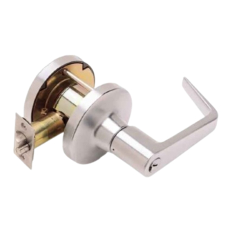
INSTALLATION INSTRUCTIONS FOR INSTALLING
T-SERIES EXTRA HEAVY DUTY LEVER LOCKSET
IMPORTANT: THIS LOCK IS NON-HANDED. LOCK IS FACTORY PACKED PREADJUSTED FOR 1³⁄₄" (45 mm)
THICK DOORS. TO ADJUST LOCK FOR OTHER DOOR THICKNESS, SEE STEP 8, 9 & 10. SPACERS MUST BE
USED FOR DOORS THINNER THAN 1³⁄₄ " (45mm) THICK. FOR FUNCTIONS T351, T381, T561 AND T571,
SEE STEPS 16 (STANDARD CYLINDER) OR 17 (IC CORE) FOR TIMING INSTRUCTIONS.
Outer Trim Assembly
Interchangeable Core Cylinder
LEFT HAND REVERSE SHOWN
STEP 1
MARK THE DOOR
Fold the template on the line indicated.
Place on HIGH EDGE of door bevel.
Position centerline of the template on heightline
(suggested height is 38" (965 mm) from floor).
A.
Locate and mark center for 2¹⁄₈" (54 mm) hole.
B.
Locate and mark positions for notches.
Caution: Notches must be horizontal.
Locate and mark center for two (2) ⁵⁄₁₆" (8 mm)
C.
through-bolt holes.
D.
Locate and mark center for 1" (25 mm) latch bolt hole
in the door edge.
Note: If steel frames are used, the latch centerline must
be in line with the center of the strike preparation.
Hint: For retrofitting of existing 2¹⁄₈" (54mm) holes, fold template in half to locate position for the two (2) ⁵⁄₁₆" (8mm) holes.
*Spacer
Chassis Assembly
Outer Trim Assembly
Standard Cylinder
Set Screw
¹⁄₄-20 x ¹⁄₄"
Mounting Screws
#10-32 x 1"
Inner Mounting Plate
*Spacer
Attaching Screws
#8 Combination
Latch Assembly
*Spacer required for all
doors less than 1³⁄₄" thick.
B) Mark Notches
A) Mark 2¹⁄₈" Hole
C) Mark Thru-Bolt Holes
Inner Lever
Rose
Inner Trim Assembly
Flanged Nut
INSIDE
OUTSIDE
DOOR HAND DETERMINED FROM OUTSIDE
High Edge Of Bevel Door
D) Mark Latch Hole
Advertisement
Table of Contents

Related Manuals for Falcon T351


Summary of Contents for Falcon T351
- Page 1 THICK DOORS. TO ADJUST LOCK FOR OTHER DOOR THICKNESS, SEE STEP 8, 9 & 10. SPACERS MUST BE USED FOR DOORS THINNER THAN 1³⁄₄ " (45mm) THICK. FOR FUNCTIONS T351, T381, T561 AND T571, SEE STEPS 16 (STANDARD CYLINDER) OR 17 (IC CORE) FOR TIMING INSTRUCTIONS.
- Page 2 Note: Use of a drill guide is recommended to ensure straight and level holes. IF USING THE FALCON OPTIONAL DRILL GUIDE Install Drill Guide (M204-198) into the door. Make certain the correct backset locators are even with door edge. Drill two (2) ⁵⁄₁₆" (8 mm) holes from both sides to the center.
- Page 3 INSTALL INNER TRIM ASSEMBLY Thru Post STEP 5 Inner Trim Asssembly Slide the inner trim assembly over the chassis spindle. Thru-posts will engage the inner trim asembly on 1 ³⁄₄ " (45 mm) thick doors. Secure to the door with two #10-32 x 1" machine screws provided. Thru Post Mounting Screws Chassis Spindle...
- Page 4 Remove the flanged nut with the black hex wrench DOOR CENTERING Gage ADJUSTMENT GAGE provided, and remove the outer mounting plate. NT FALCON T-SERIES LEVER LOCKS FOR DOORS LESS THAN Flanged Nut 1 3/4 (45mm) THICK Inner Mounting Plate Place the spacer on over the outer chassis spindle...
- Page 5 IC CORE AND TAILPIECE STEP 12 Be certain to use the correct tailpiece with the core. Six pin cores should only use the "6P" tailpiece. 7 Pin Core 6 Pin Core Seven pin cores should only use the "7P" tailpiece. STEP 13 TO REMOVE ALL CYLINDER LEVERS (Except Interchangeable Core)
- Page 6 STEP 16 TIMING INSTRUCTIONS FOR STANDARD CYLINDER LOCKS FOR THE FOLLOWING FUNCTIONS: T351, T381, T561, T571 RH Shown If the cylinder and lever are installed, refer to Step 13 for Action lever removal instructions. Using a thin flat screw driver, turn the action bar slot clockwise slot (cw) until it stops at about 2:00.
Need help?
Do you have a question about the T351 and is the answer not in the manual?
Questions and answers