
Related Manuals for Magliner CooLift CTA43


Summary of Contents for Magliner CooLift CTA43
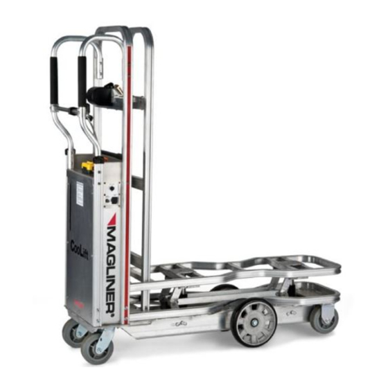
- Page 1 CooLift ® Service Manual IMPORTANT: Read entire manual before operating Serial #: ________________________________ Date of Purchase: ________________________ 1-800-MAGLINE (624-5463) Page 1 www.magliner.com...
-
Page 2: Table Of Contents
Changing Hydraulic Pump ......................44-45 Changing Hydraulic Cylinder ......................46-47 Bleeding Hydraulic System......................48-49 Replacing Brake Pawl ........................50-51 Relocating Master Cylinder .........................51 Troubleshooting ..........................52-53 Replacement Parts List ......................... 54-56 Inspection / Maintenance Checklist....................57-63 1-800-MAGLINE (624-5463) Page 2 www.magliner.com... -
Page 3: Coolift Toolkit
Absorbing material (kitty litter) DOT 3 or DOT 4 brake fluid • Hydraulic fluid • • Shop towels • Tube of clear silicone sealant • Medium strength thread locker • Flashlight • Hydraulic thread sealant • Utility knife 1-800-MAGLINE (624-5463) Page 3 www.magliner.com... -
Page 4: Vertical Loop Handle Removal
8) Tighten the remaining previously hand tightened screws with #3 Phillips screwdriver and 7/16” wrench. 9) Position the master cylinder (J) into place on the horizontal brace (E) and tighten the two mounting screws with the Torx T30 driver. 1-800-MAGLINE (624-5463) Page 4 www.magliner.com... - Page 5 Pan head machine screw - 1/4”-20 x 3” long (top K screws for 80111 CTA48 model - bottom two K screws are 80108) Rotate loop handle In toward center to remove Rotate loop handle out to replace 1-800-MAGLINE (624-5463) Page 5 www.magliner.com...
-
Page 6: Bulk Head Removal And Installation
(J) using the #4 Phillips screwdriver and the 1/2” wrench. 8) Securely tighten the four screws (G) in the bulk head saddle plate (B) using the #3 Phillips screwdriver and the 7/16” wrench. 1-800-MAGLINE (624-5463) Page 6 www.magliner.com... - Page 7 F Hex lock nut - 3/8”-16 80603 G Screw - 1/4”-20 x 2-3/4” long 80111 H Hex lock nut - 1/4”-20 80675 Screw - 5/16”-18 x 1” long 80313 J Hex lock nut - 5/16”-18 80676 Completed assembly 1-800-MAGLINE (624-5463) Page 7 www.magliner.com...
- Page 8 (E) and 3/8”-16 lock nut (F) and securely tighten using the two 9/16” wrenches. 7) Once all items are in place, securely tighten the hardware for the bulk head saddle plate and for the hardware connecting the bulk head to the base plate 1-800-MAGLINE (624-5463) Page 8 www.magliner.com...
- Page 9 E Screw - 3/8”-16 x 1-1/2” long 79988 F Hex lock nut - 3/8”-16 80603 G Screw - 1/4”-20 x 2-3/4” long 80111 H Hex lock nut - 1/4”-20 80675 Screw - 3/8”-16 x 1-1/4” long 80026 Figure 2 1-800-MAGLINE (624-5463) Page 9 www.magliner.com...
-
Page 10: Replacing Foam Handle Sleeve
5) With the handle held securely in a vise, gradually work the new sleeve into place by twisting, pulling and sliding, taking care not to rip the foam. Part # 302285 1-800-MAGLINE (624-5463) Page 10 www.magliner.com... -
Page 11: Replacing Pallet Stops
A Screw - 5/16”-18 x 1-1/4” long 80012 B Pallet stop 309206 C Hex lock nut - 5/16”-18 80676 Quantities listed are for both sides of the CooLift CTA43 CTA48 Figure 2 309206 Figure 1 1-800-MAGLINE (624-5463) Page 11 www.magliner.com... -
Page 12: Replacing Vertical Handle Mount Assembly
309087 B Screw - 1/4”-20 x 2-1/2” long 80108 C Screw - 5/16”-18 x 1-1/2” long 80115 D Screw - 1/4”-20 x 1-1/2” long 80105 Hardware quantities listed are for one side of the CooLift 1-800-MAGLINE (624-5463) Page 12 www.magliner.com... -
Page 13: Replacing Brushes
9) Place the back access panel back into position and secure using the previously removed mounting screws (B) with the #3 Phillips head screwdriver. Item Qty Part Number A Yoke brush 309259 Screw - 1/4”-20 x 3/4” long w/ 80257 locking patch 1-800-MAGLINE (624-5463) Page 13 www.magliner.com... -
Page 14: Replacing Front Caster
309098 Axle assembly (includes E) 84501 Carriage bolt - 3/8”-16 x 1” long 80127 Carriage nut (included in 84501) Caster wheel - 6” x 2” flat tread 130014 Quantities listed are for each front caster 1-800-MAGLINE (624-5463) Page 14 www.magliner.com... -
Page 15: Replacing Rear Swivel Caster
Hex head cap screw - 3/8”-16 x 80025 1” long Hex lock nut flange - 3/8”-16 80624 Caster assembly - 6” x 2” swivel 130066 grey flat tread Quantities listed are for each rear swivel caster 1-800-MAGLINE (624-5463) Page 15 www.magliner.com... -
Page 16: Replacing Containment Strap And Tongue
(J) and lock nut (H), allowing the tongue to rotate freely. Front Underside Part View Item Qty. Number Hex lock nut w/ nylon insert - 80683 #10-24 UNC Containment strap tongue 309133 Screw - #10-24 x 2-1/2” long 80004 1-800-MAGLINE (624-5463) Page 16 www.magliner.com... -
Page 17: Replacing Battery Box
A Screw - 1/4”-20 x 3/4” long w/ locking patch 80257 B Back access panel 309077 C Battery box assembly 309100 D Wiring harness 62023 E Battery box handle F AC charger output cord plug 1-800-MAGLINE (624-5463) Page 17 www.magliner.com... -
Page 18: Changing Battery Cells
D Wiring harness for battery interconnect 62024 E Grommet - 5/8” ID x 1-1/8” OD x 3/8” wide 309024 F Battery cell - 12v - 18Ah 61018 G Wiring harness 62023 1-800-MAGLINE (624-5463) Page 18 www.magliner.com... - Page 19 CooLift ® (top battery cell) CHARGING PORT (bottom battery cell) TOP BATTERY BOTTOM BATTERY 1-800-MAGLINE (624-5463) Page 19 www.magliner.com...
-
Page 20: Replacing Deck Positioning (Up/Down) Switch
A Operator up/down switch 63019 B Cord grip PG-16 (includes D and E) 309122 C Hex locknut PG-16 309123 D Jam nut E Rubber insert F Plug connector G Solenoid H Washer, neoprene bonded 80730 1-800-MAGLINE (624-5463) Page 20 www.magliner.com... - Page 21 CooLift ® Black wire to solenoid battery post White wire to solenoid start post Green wire to pump valve coil 1-800-MAGLINE (624-5463) Page 21 www.magliner.com...
-
Page 22: Replacing Battery Charger
- Confirm the input power cord is securely plugged into the charger receptacle. 15) Replace the back access panel using the mounting screws and #3 Phillips head screwdriver. Figure 3 ON/OFF switch Figure 2 Figure 1 1-800-MAGLINE (624-5463) Page 22 www.magliner.com... - Page 23 Black or blue wire to terminal with copper screw terminal c. White or brown wire to silver screw terminal Note: Review wiring part diagram to confirm correct wire-terminal connection. iii. Reassemble cord plug and securely tighten cord grip clamp. 1-800-MAGLINE (624-5463) Page 23 www.magliner.com...
- Page 24 Wiring Part Diagram Item Description Qty. Part # Cord grip - PG-9 309177 Hex lock nut - PG-9 309178 Electrical cord 8’ long with C13 connector on one end 64018 Plug 115v 5-15p three-prong cord plug 61053 1-800-MAGLINE (624-5463) Page 24 www.magliner.com...
-
Page 25: Replacing Foam Mounting Strips
10) Replace the back access panel using the mounting screws and #3 Phillips head screwdriver. Item Description Qty. Part # 3/4” square foam tape, adhesive 309217 backed - 4” long Figure 1 1-800-MAGLINE (624-5463) Page 25 www.magliner.com... -
Page 26: Replacing Battery Meter
14. Recheck all connections for correct wiring placement and tightness. 15. Reinstall the battery box (see Replacing Battery Box in the CooLift Service Manual). Description Qty. Part Number Battery charge meter 62033 Press tabs inward Figure 1 Figure 3 Figure 2 1-800-MAGLINE (624-5463) Page 26 www.magliner.com... -
Page 27: Replacing Power Switch Or Circuit Breaker
7) Recheck all connections for correct wiring placement and tightness. (-) To Battery 8) Reinstall battery box (see Replacing Battery (-) To (+) To Battery Pump Box). Switch Battery Meter Breaker White (+) To Pump Relay 1-800-MAGLINE (624-5463) Page 27 www.magliner.com... -
Page 28: Changing Wiring Harness
Wiring harness to connect battery box to on/off toggle switch 62023 Wiring harness for battery interconnect 62024 Wiring harness for battery box connector plug 62025 Wiring harness for battery charge meter 62032 Battery charge meter 62031 1-800-MAGLINE (624-5463) Page 28 www.magliner.com... - Page 29 Battery box power wire (E) cord red (+) wire (I) Charger port black (-) wire (F) Charger port red Circuit breaker (+) wire (H) Circuit breaker wire (N) Pump red (+) wire (J) 62030 Electrical Schematic 1-800-MAGLINE (624-5463) Page 29 www.magliner.com...
-
Page 30: Changing Axle
15) With the caliper mounting screws (H) lightly hand tightened, engage the holding brake to correctly position the caliper orientation to the brake disc. Then the bolts may be tightened using the 5mm Allen wrench. 1-800-MAGLINE (624-5463) Page 30 www.magliner.com... - Page 31 F Washer 80718 G Brake disc 309050 H Hex socket head cap screw - M6 x 20mm 80003 Side rail Brake caliper assembly 309594 Quantities listed for items B-J are for one side of the CooLift 1-800-MAGLINE (624-5463) Page 31 www.magliner.com...
-
Page 32: Changing Brake Caliper
13) Slide brake pads into the top window of the caliper until they come to a stop (see Figure 3). 14) Using a 2.5mm Allen wrench install and tighten the pad retaining pin. Pad pin torque should be 10 1-800-MAGLINE (624-5463) Page 32 www.magliner.com... - Page 33 C Brake disc 309050 D Caliper assembly 309595 Caliper brake line assembly (includes F, G 309145 and H) Banjo bolt 80135 O-rings Banjo fitting on brake line Quantities listed are for one side of the CooLift 1-800-MAGLINE (624-5463) Page 33 www.magliner.com...
-
Page 34: Changing Brake Pad
This will give you more room to fit in the new pads. Walk the piston back and forth until the piston is all the way back in the bore. Do the same thing on the other side. NOTE: Do not push the edge of the piston as they may crack or chip. 1-800-MAGLINE (624-5463) Page 34 www.magliner.com... - Page 35 Inserting the pads Item Qty. Part Number A Hex socket head cap screw - M6 x 20mm 80003 B Pair of brake pads 309594 C Caliper assembly 309595 Quantities listed are for one side of the CooLift 1-800-MAGLINE (624-5463) Page 35 www.magliner.com...
-
Page 36: Changing Upper Brake Line
(H) and tighten with the 12mm wrench. 14) Connect the other end to the master cylinder in the same manner. 15) Bleed the brake system (see Bleeding the Brakes). 16) Reinstall the battery box (see Replacing Battery Box). 1-800-MAGLINE (624-5463) Page 36 www.magliner.com... - Page 37 A Master cylinder 309218 Cord grip - PG-21 309124 C Hex lock nut - PG-21 309125 D Master cylinder brake line 309083 Junction block 309051 Copper washer 80712 G Banjo bolt 80124 H Banjo fitting 1-800-MAGLINE (624-5463) Page 37 www.magliner.com...
-
Page 38: Changing Lower Brake Line
10) Connect the new brake line (B) to the junction block (F) using the 8mm wrench and reroute it through in the same locations as the line to be replaced. 11) Bleed the brake system (see Bleeding the Brakes). 12) Reinstall the battery box (see Replacing Battery Box). 1-800-MAGLINE (624-5463) Page 38 www.magliner.com... - Page 39 6) Return brake line to inside of clip. Push the longer side of the clip top down towards the brake line to close the clip. Open position Closed position Item Qty. Part Number Brake line clip 61019 1-800-MAGLINE (624-5463) Page 39 www.magliner.com...
-
Page 40: Replacing Brake Master Cylinder
10) Check the brake system for proper functioning. 11) If the system seems to be squishy or not functioning properly there may be some air trapped in the lines and they will need to be bled (see Bleeding the Brakes). 1-800-MAGLINE (624-5463) Page 40 www.magliner.com... - Page 41 F Master cylinder brake line (includes G) 309083 G Banjo fitting Quantities listed are for quantities shown - 2 additional 80712 and 1 additional 80124 are used at the lower end of the master cylinder brake line 1-800-MAGLINE (624-5463) Page 41 www.magliner.com...
-
Page 42: Bleeding Brakes
T10 torx driver until fluid is noticed seeping out of the bleed screw. NOTE: It is not necessary to take the bleed screw out entirely, it just needs to be loosened a few turns to allow the air in the brake line to 1-800-MAGLINE (624-5463) Page 42 www.magliner.com... - Page 43 - an additional 80124 is Caliper bleed screw 80135 used at the top of the master Junction block 309051 cylinder line assembly Master cylinder brake line 309083 Banjo bolt 80124 Caliper brake line assembly 309145 1-800-MAGLINE (624-5463) Page 43 www.magliner.com...
-
Page 44: Changing Hydraulic Pump
11) Reconnect each wiring harness (B) to pump connections using the 10mm and 13mm wrenches. 12) Reinstall the battery box (see Replacing Battery Box). 13) The hydraulic system should be purged of all air within the system (see Bleeding the Hydraulic System). 1-800-MAGLINE (624-5463) Page 44 www.magliner.com... - Page 45 Figure 3 80261 x 3/4” long Pan head machine screw - 1/4”-20 80257 x 3/4” long w/ locking patch G Manual pump handle 63014 H Hydraulic pump reservoir 59501 Pump starter - 24v DC (solenoid) 63015 1-800-MAGLINE (624-5463) Page 45 www.magliner.com...
-
Page 46: Changing Hydraulic Cylinder
11. Pour hydraulic fluid from old cylinders into the pump reservoir. 12. Turn on the power switch. 13. Elevate the cylinders to maximum height using the electric pump. Make certain the cylinder top fits properly in the mounting bracket in the CooLift deck. 1-800-MAGLINE (624-5463) Page 46 www.magliner.com... - Page 47 H Fitting - union or coupling 55413 Cylinder assembly (includes 55417 fitting, 59006 80396 screw and 80754 washer) J Fitting - flare to NPT 55417 K Fitting - NPT to flare 55401 Cylinder mount screw (not shown) 80010 1-800-MAGLINE (624-5463) Page 47 www.magliner.com...
-
Page 48: Bleeding Hydraulic System
8) Using the 3/16” or 9/64” Allen wrench, loosen the bleed screw on the front cylinder by three com- plete revolutions. • For Rev H cylinders, loosen the bleed screw 1/4 turn. • For all other cylinders, loosen the bleed screw by three complete revolutions. 1-800-MAGLINE (624-5463) Page 48 www.magliner.com... - Page 49 Slotted truss head screw 3/8”-16 X 3/4” 80396 Helical lock washer 3/8” dia x 1/8” thick 80754 Hydraulic fluid 55407 Hydraulic fluid additive 2 oz. 55418 (Fill to 1/2 inch below the top when the deck is at the lowest position) 1-800-MAGLINE (624-5463) Page 49 www.magliner.com...
-
Page 50: Replacing Brake Pawl
Pan head machine screw - #10-32 UNF x 1” long 80123 Flat washer for #10 screw 80763 Hex lock nut 10-32UNF thread 80684 Round head machine screw - #10-32 UNF x 7/8” long 80122 Lock washer split for #10 screw 80747 Cable tie 61052 1-800-MAGLINE (624-5463) Page 50 www.magliner.com... -
Page 51: Relocating Master Cylinder
4) The master cylinder can now be slid into another location. NOTE: Keep the master cylinder upright during this process to keep from introducing air into the brake system. 5) Tighten the screws to secure the master cylinder in the new location. FASTENING SCREWS JAM NUT 1-800-MAGLINE (624-5463) Page 51 www.magliner.com... -
Page 52: Troubleshooting
Have all electrical connections been checked? Is the internal charger switch in the ON position? Is the power plug plugged in the charger socket? Is the charger output cord plugged into the battery pack charger port? 1-800-MAGLINE (624-5463) Page 52 www.magliner.com... - Page 53 Check the continuity of the operator on/off switch. Hydraulic or brake fluid has dripped into the drip pan underneath the CooLift deck. Wipe up any fluid that may have leaked into the drip pan using shop towels. 1-800-MAGLINE (624-5463) Page 53 www.magliner.com...
-
Page 54: Replacement Parts List
Cord grip - PG-16 309122 Cord grip - PG-21 309124 Cord grip hex lock nut - PG-9 309178 Cord grip hex lock nut - PG-16 309123 Cord grip hex lock nut - PG-21 309125 Corner post assembly 309108 1-800-MAGLINE (624-5463) Page 54 www.magliner.com... - Page 55 Pan head machine screw - 1/4”-20 x 3/4” long with locking patch 80257 Pan head machine screw - 1/4”-20 x 1” long 80102 Pan head machine screw - 1/4”-20 x 1-1/2” long 80105 Pan head machine screw - 1/4”-20 x 1-3/4” long 80106 1-800-MAGLINE (624-5463) Page 55 www.magliner.com...
- Page 56 Wiring harness to connect cabinet charge port to on/off toggle switch 62030 Wiring harness to connect circuit breaker to on/off toggle switch 62020 Wiring harness to connect circuit breaker to pump 62022 Wiring harness to connect pump to on/off toggle switch 62021 Yoke brush 309259 1-800-MAGLINE (624-5463) Page 56 www.magliner.com...
-
Page 57: Inspection / Maintenance Checklist
CooLift ® 1-800-MAGLINE (624-5463) Page 57 www.magliner.com... - Page 58 CooLift ® 1-800-MAGLINE (624-5463) Page 58 www.magliner.com...
- Page 59 CooLift ® 1-800-MAGLINE (624-5463) Page 59 www.magliner.com...
- Page 60 CooLift ® 1-800-MAGLINE (624-5463) Page 60 www.magliner.com...
- Page 61 CooLift ® 1-800-MAGLINE (624-5463) Page 61 www.magliner.com...
- Page 62 CooLift ® 1-800-MAGLINE (624-5463) Page 62 www.magliner.com...
- Page 63 CooLift ® 1-800-MAGLINE (624-5463) Page 63 www.magliner.com...
- Page 64 CooLift ® MAGLINE INC. ® Standish, Michigan 48658 1-800-MAGLINE (624-5463) www.magliner.com Form # B9243 May 2018 REV CooLift ® is a registered trademark owned by © Copyright 2009-2018, Magline, Inc. Swift Water Logistics Patent: www.magliner.com/patents 1-800-MAGLINE (624-5463) Page 64 www.magliner.com...
Need help?
Do you have a question about the CooLift CTA43 and is the answer not in the manual?
Questions and answers