Sony CDX-G1200U Service Manual
Fm/am compact disc player
Hide thumbs
Also See for CDX-G1200U:
- Operating instructions manual (29 pages) ,
- Operating instructions manual (56 pages) ,
- Operating instructions manual (192 pages)
Table of Contents
Advertisement
SERVICE MANUAL
Ver. 1.0 2016.08
The service manual of the mechanism deck, used in
this model, has been issued in a separate volume.
Please refer to the service manual of the MG-101
series for the mechanism deck information.
• The tuner and CD sections have no adjustments.
(US, CND)
FOR THE CUSTOMERS IN THE USA. NOT
APPLICABLE IN CANADA, INCLUDING IN
THE PROVINCE OF QUEBEC.
POUR LES CLIENTS AUX ÉTATS-UNIS.
NON APPLICABLE AU CANADA, Y
COMPRIS LA PROVINCE DE QUÉBEC.
AUDIO POWER SPECIFICATIONS
CTA2006 Standard
Power Output: 20 Watts RMS × 4
at 4 Ohms < 1% THD+N
SN Ratio: 80 dBA
(reference: 1 Watt into 4 Ohms)
Tuner section
(US, CND)
FM
Tuning range: 87.5 MHz – 107.9 MHz
Antenna (aerial) terminal:
External antenna (aerial) connector
Intermediate frequency:
FM CCIR: -1,956.5 kHz to -487.3 kHz and
+500.0 kHz to +2,095.4 kHz
Usable sensitivity: 7 dBf
Selectivity: 75 dB at 400 kHz
Signal-to-noise ratio: 73 dB
Separation: 50 dB at 1 kHz
Frequency response: 20 Hz – 15,000 Hz
AM
Tuning range: 530 kHz – 1,710 kHz
Antenna (aerial) terminal:
External antenna (aerial) connector
Sensitivity: 26 μV
(AEP, UK, HK)
FM
Tuning range:
When [AREA] is set to [EUROPE]:
87.5 MHz – 108.0 MHz
When [AREA] is set to [RUSSIA]:
FM1/FM2: 87.5 MHz – 108.0 MHz
(at 50 kHz step)
FM3: 65 MHz – 74 MHz (at 30 kHz step)
Antenna (aerial) terminal:
External antenna (aerial) connector
Intermediate frequency:
When [AREA] is set to [EUROPE]:
FM CCIR: -1,956.5 kHz to -487.3 kHz and
+500.0 kHz to +2,095.4 kHz
When [AREA] is set to [RUSSIA]:
FM CCIR: -1,956.5 kHz to -487.3 kHz and
+500.0 kHz to +2,095.4 kHz
FM OIRT: -1,815.6 kHz to -943.7 kHz and
+996.6 kHz to +1,776.6 kHz
Usable sensitivity: 7 dBf
Selectivity: 75 dB at 400 kHz
Signal-to-noise ratio: 73 dB
Separation: 50 dB at 1 kHz
Frequency response: 20 Hz – 15,000 Hz
9-896-303-01
2016H33-1
Sony Video & Sound Products Inc.
©
2016.08
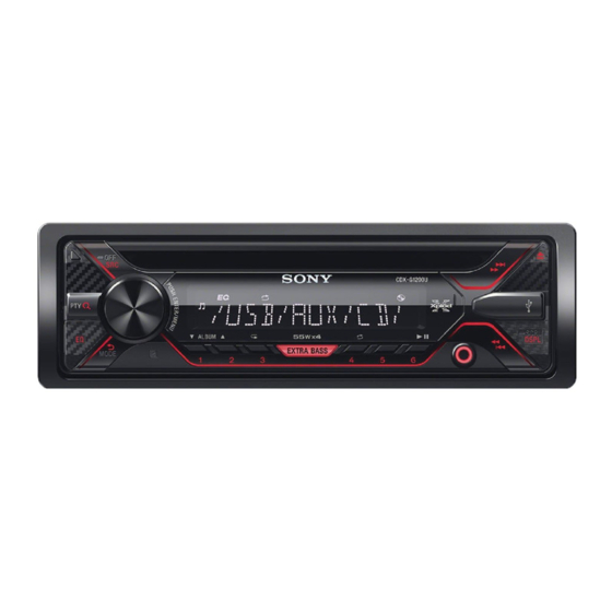
Photo: CDX-G1200U
Model Name Using Similar Mechanism
Mechanism Type
Optical Pick-up Name
SPECIFICATIONS
MW/LW
SW
Tuning range:
Tuning range:
MW: 531 kHz – 1,602 kHz
SW1: 2,940 kHz – 7,735 kHz
LW: 153 kHz – 279 kHz
SW2: 9,500 kHz – 18,135 kHz
Antenna (aerial) terminal:
(except for 10,140 kHz – 11,575 kHz)
External antenna (aerial) connector
Antenna (aerial) terminal:
External antenna (aerial) connector
Sensitivity: MW: 26 μV, LW: 50 μV
Intermediate frequency:
-2,463.8 kHz to -1,710.1 kHz and
(E, AR, KR, AUS)
+1,710.0 kHz to +2,418.4 kHz
FM
Sensitivity: 26 μV
Tuning range:
87.5 MHz – 108.0 MHz (at 50 kHz step)
CD Player section
87.5 MHz – 108.0 MHz (at 100 kHz step)
87.5 MHz – 107.9 MHz (at 200 kHz step)
Signal-to-noise ratio: 95 dB
For Argentine models:
Frequency response: 10 Hz – 20,000 Hz
87.5 MHz – 107.9 MHz
Wow and flutter: Below measurable limit
FM tuning step (except for Argentine
The maximum number of: (CD-R/CD-RW
models):
only)
50 kHz/100 kHz/200 kHz switchable
–folders (albums): 150 (including root
Antenna (aerial) terminal:
folder)
External antenna (aerial) connector
–files (tracks) and folders: 300 (may less
Intermediate frequency:
than 300 if folder/file names contain many
FM CCIR: -1,956.5 kHz to -487.3 kHz and
characters)
+500.0 kHz to +2,095.4 kHz
–displayable characters for a folder/file
Usable sensitivity: 7 dBf
name: 32 (Joliet)/64 (Romeo)
Selectivity: 75 dB at 400 kHz
Corresponding codec: MP3 (.mp3) and WMA
Signal-to-noise ratio: 73 dB
(.wma)
Separation: 50 dB at 1 kHz
Frequency response: 20 Hz – 15,000 Hz
AM
Tuning range:
531 kHz – 1,602 kHz (at 9 kHz step)
US, Canadian, E, Argentina, Korean, Indian and Australian models
530 kHz – 1,710 kHz (at 10 kHz step)
For Argentine models:
530 kHz – 1,710 kHz
AM tuning step (except for Argentine
models):
9 kHz/10 kHz switchable
Antenna (aerial) terminal:
External antenna (aerial) connector
Sensitivity: 26 μV
(EA)
FM
Tuning range: 87.5 MHz – 108.0 MHz
Antenna (aerial) terminal:
External antenna (aerial) connector
Intermediate frequency:
FM CCIR: -1,956.5 kHz to -487.3 kHz and
+500.0 kHz to +2,095.4 kHz
Usable sensitivity: 7 dBf
Selectivity: 75 dB at 400 kHz
Signal-to-noise ratio: 73 dB
Separation: 50 dB at 1 kHz
Frequency response: 20 Hz – 15,000 Hz
MW
Tuning range: 531 kHz – 1,602 kHz
Antenna (aerial) terminal:
External antenna (aerial) connector
Sensitivity: 26 μV
CDX-G1200U/G1201U/
G1202U/G1280UM
Saudi Arabia Model
USB Player section
Interface: USB (Full-speed)
Maximum current: 500 mA
The maximum number of recognizable
tracks:
–folders (albums): 256
–files (tracks) per folder: 256
Compatible Android Open Accessory
protocol (AOA): 2.0
Corresponding codec:
MP3 (.mp3)
Bit rate: 8 kbps – 320 kbps (Supports
VBR (Variable Bit Rate))
Sampling rate: 16 kHz – 48 kHz
WMA (.wma)
Bit rate: 32 kbps – 192 kbps (Supports
VBR (Variable Bit Rate))
Sampling rate: 32 kHz, 44.1 kHz,
48 kHz
FLAC (.flac)
Bit depth: 16 bit, 24 bit
Sampling rate: 44.1 kHz, 48 kHz
Power amplifier section
Output: Speaker outputs
Speaker impedance: 4 Ω – 8 Ω
Maximum power output: 55 W × 4 (at 4 Ω)
FM/AM COMPACT DISC PLAYER
FM/MW/LW COMPACT DISC PLAYER
FM/MW/SW COMPACT DISC PLAYER
US Model
Canadian Model
Australian Model
Hong Kong Model
Argentina Model
CDX-G1200U
AEP Model
UK Model
CDX-G1200U/G1201U/G1202U
E Model
Korean Model
CDX-G1200U/G1201U
Indian Model
CDX-G1200U/G1280UM
CDX-G1100U/G1150U/G3100UP
MG-101CF-188
DAX-25A
General
Outputs:
Audio outputs terminal (REAR, SUB)
Power antenna (aerial)/Power amplifier
control terminal (REM OUT)
Inputs:
Remote controller input terminal
Antenna (aerial) input terminal
AUX input jack (stereo mini jack)
USB port
Power requirements: 12 V DC car battery
(negative ground (earth))
Rated current consumption: 10 A
Dimensions:
Approx. 178 mm × 50 mm × 177 mm
(7
1
/
in × 2 in × 7 in) (w/h/d)
8
Mounting dimensions:
Approx. 182 mm × 53 mm × 160 mm
(7
1
/
in × 2
1
/
in × 6
5
/
in) (w/h/d)
4
8
16
Mass: Approx. 1.2 kg (2 lb 11 oz)
Package contents:
Main unit (1)
Remote commander (1): RM-X211
(Except AEP, UK, HK)
Parts for installation and connections
(1 set)
Design and specifications are subject to
change without notice.
AEP, UK and Hong Kong models
Saudi Arabia model
Advertisement
Table of Contents


Need help?
Do you have a question about the CDX-G1200U and is the answer not in the manual?
Questions and answers