Table of Contents
Advertisement
Quick Links
Advertisement
Table of Contents

Related Manuals for Bertin Technologies Coriolis m


Summary of Contents for Bertin Technologies Coriolis m
-
Page 2: Table Of Contents
NTRODUCTION ® Coriolis µ INDEX 1 Introduction ....................3 Safety information ..........................3 Warranty ............................5 Manufacturer information ........................5 Technical support ..........................5 ® 2 Description of Coriolis µ Air Sampler ............6 Product overview..........................6 Presentation of the Keypad .......................7 Setting ...............................7 Technical features ..........................8 Operating principle ..........................9 Normative requirements ........................9 3 Transport / Storage ..................10... -
Page 3: Introduction
NTRODUCTION ® Coriolis µ 1 Introduction This user manual includes the required information regarding installation, operation and maintenance of ® the Coriolis µ Air Sampler. The product’s technical specifications and the following information may change without prior notice. 1.1 Safety information ®... - Page 4 NTRODUCTION ® Coriolis µ is not responsible for any damage or injury that may occur as a result of ERTIN ECHNOLOGIES operating the instrument in a different way as described in this document. 1.1.3 Biological risks To prevent any risk of contamination, wear gloves when handling samples and follow strictly the safety instructions related to biohazardous agents.
-
Page 5: Warranty
NTRODUCTION ® Coriolis µ 1.2 Warranty certifies that this product is free of defects at the time of shipment. ERTIN ECHNOLOGIES This warranty is limited to a period of one (1) year and does not cover the cane, the air intake and the battery. -
Page 6: Description Of Coriolis
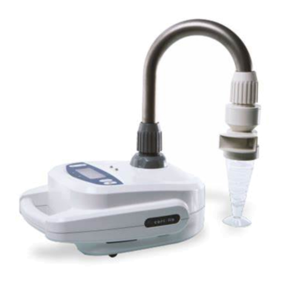
® ESCRIPTION OF ORIOLIS µ AMPLER ® Coriolis µ ® 2 Description of Coriolis µ Ai r Sampler 2.1 Product overview ® Coriolis µ is a cyclonic system air sampler used to collect biological airborne particles for air monitoring. ® Coriolis µ... -
Page 7: Presentation Of The Keypad
® ESCRIPTION OF ORIOLIS µ AMPLER ® Coriolis µ 2.2 Presentation of the Keypad The LCD screen lights up when the unit is switched on. The keypad allows the user to set and start runs. The keypad consists in a 4-line-LCD screen, 4 buttons and 2 LEDs (see below): Screen/display Up button Valid button... -
Page 8: Technical Features
® ESCRIPTION OF ORIOLIS µ AMPLER ® Coriolis µ 2.4 Technical features Technical characteristics Power requirements 100 - 240 V, 2A, 50 - 60 Hz Power consumption 140 W Size / weight (Air sampler alone) Width 220 mm Length 300 mm Height 180 mm Height with the cane... -
Page 9: Operating Principle
® ESCRIPTION OF ORIOLIS µ AMPLER ® Coriolis µ 2.5 Operating principle ® Coriolis patented technology is highly innovative: based on a cyclone type operation, it concentrates airborne biological particles into a liquid sample. Air is first aspirated into the cone (pre-filled with collection liquid) in a whirling motion to form a vortex. Particles are pulled against the wall due to centrifugal force and separated from air to be concentrated in the liquid. -
Page 10: Transport / Storage
RANSPORT TORAGE ® Coriolis µ 3 Transport / Storage 3.1 Transport Avoid violent shocks that may damage the equipment. To transport the equipment, use the appropriate case: delivery box or optional transport box. 3.2 Storage The unit must be stored in a dry area at a temperature from +0°C to +50°C. Page 10/33... -
Page 11: Installation
NSTALLATION ® Coriolis µ 4 Installation WARNING : DO NOT connect the unit to the mains supply before the installation is over. 4.1 Unpacking 1. Remove the equipment from the case and place it on a clean, horizontal and stable surface. 2. -
Page 12: Recommendations
DO NOT fill in the cone with more than 15 ml of collection liquid. The optimal air flow rate is 300 l/min. DO NOT USE NON RECOMMENDED COLLECTION LIQUID (Bertin Technologies recommended sterile water or Braun water with Triton or Tween in low concentration). -
Page 13: Instructions For Use
NSTRUCTIONS FOR USE ® Coriolis µ 5 Instructions for use 5.1 Turning on the equipement Turn the unit ON by pressing the “Valid” button (around 3 seconds), until the home screen is displayed: CORIOLIS Name of the equipment 02.-- Software version CORIOLIS... - Page 14 NSTRUCTIONS FOR USE ® Coriolis µ 5.2.1 Clock The equipment can be used but it is not possible to set the collection time. Be aware that you will have to check the time yourself during collection. Turn off the equipment by pressing the “Valid” button and re-start the equipment. If the error still occurs, please contact the manufacturer.
-
Page 15: Using Parameters For "Stand Alone" Mode
NSTRUCTIONS FOR USE ® Coriolis µ 5.3 Using parameters for “stand alone” mode 5.3.1 Ac cessing to the set up menu After the autotests, the set up menu is automatically displayed with the menu screen: 10 :15 10/01/07 COLLECT >> SETUP <<... - Page 16 NSTRUCTIONS FOR USE ® Coriolis µ The “DELAY” value flashes: it is the waiting time set before starting the run. It ranges from 0 to 100 min by increments of 1min (up to 10min), then 10 min (up to 100min). Press the “Valid”...
- Page 17 NSTRUCTIONS FOR USE ® Coriolis µ 5.3.3.2 Start a sampling run The run starts: If a delay is set, the delay time is displayed: an elapsed time counter (in minutes and seconds) counts down the delay. If not, the collection time is displayed: an elapsed time counter (in minutes and seconds) counts down the time remaining before the end of the run.
- Page 18 NSTRUCTIONS FOR USE ® Coriolis µ 5.3.3.4 Stop a sampling run The operator can stop the run by pressing the “Cancel” button at any time during the run. The red led lights on and the screen displays: 10:15 10/01/07 STOP PROCESS >>...
-
Page 19: Using Parameters For "Long Time Monitoring" Mode
NSTRUCTIONS FOR USE ® Coriolis µ 5.4 Using parameters for “long time monitoring” mode 5.4.1 Connection of the air sampler to the platform The sampler is placed as shown hereunder Place the sampler on the platform and connect the pump wire ... - Page 20 NSTRUCTIONS FOR USE ® Coriolis µ 10 :15 10/01/07 >>> PRIMING <<< To start the pump, press the “Valid” button until the collection liquid reaches the injection pipe of the air intake. To return to the set up menu, press on “Down” button. 5.4.4 Ac cessing to the set up menu After the autotests, the set up menu is automatically displayed with the menu screen:...
- Page 21 NSTRUCTIONS FOR USE ® Coriolis µ The “TIME” value flashes: it represents the run duration and ranges from 1 to 10 minutes by increments of 1 minute, then from 10 minutes to 120 minutes by increments of 10 minutes, then from 120 minutes to 360 minutes by increments of 30 minutes FLOW : 300 l/min...
- Page 22 NSTRUCTIONS FOR USE ® Coriolis µ 5.4.6 Sampling 5.4.6.1 Prepare a sampling run To start a run, place the selection cursor on the line “COLLECT” on the main menu display. Then, the following screen is displayed: 10 :15 10/01/07 >>> START <<<...
- Page 23 NSTRUCTIONS FOR USE ® Coriolis µ 5.4.6.3 Pause during a sampling run Pressing on the “Valid” button during the run allows suspending momentarily the collection (without modifying the effective time of collection) and to readjust if necessary the injection parameter. The following screen is displayed: 10 :15 10/01/07...
- Page 24 NSTRUCTIONS FOR USE ® Coriolis µ 5.4.6.5 Stop a sampling run The operator can stop the run by pressing the “Cancel” button at any time during the run. The red led lights on and the screen displays: 10:15 10/01/07 STOP PROCESS >>...
-
Page 25: Run Failure
NSTRUCTIONS FOR USE ® Coriolis µ 5.5 Run failure Potential cause Solution Change battery or plug the Empty battery equipment on mains supply Check if the air intake and the exhaust are not obstructed Technical problem (engine, Start a new run electronics, abnormal noise…) If the problem still occurs, please contact the... -
Page 26: Battery Supply
NSTRUCTIONS FOR USE ® Coriolis µ 5.6 Battery supply The equipment can be either used on mains supply or on battery. Even if you do not use the battery, be sure to maintain it charged in order to keep its autonomy capacity. WARNING : Always put the battery charged before turning on the equipment or re-start the equipment to detect the “battery”... -
Page 27: Administrator Menu
NSTRUCTIONS FOR USE ® Coriolis µ Administrator Menu The administrator menu allows to set up time and date, and to access to the decontamination menu of the equipment. To access this menu press the “Cancel” button for 3 seconds on the main menu “COLLECT / SET UP”. This screen is displayed: ... -
Page 28: Flow Control Option
ONTROL PTION ® Coriolis µ 6 Flow Control Option 6.1 Flow Control Option overview ® The Coriolis flow control accessory is an optical tachymeter designed to measure the rotation ® speed of the motor of the Coriolis µ. An interface part has been designed to place the accessory at a correct distance and angle from the input blade of the motor. -
Page 29: Maintenance Of The Flow Control Option
ONTROL PTION ® Coriolis µ Button On / Off ® Start the Coriolis µ at 300l/min and wait until the speed becomes stabilized (10 to 15 seconds). Press and hold the button ON/OFF on the tachymeter: the speed will be displayed. Read and note the value on the report (in rot/min). -
Page 30: Cleaning & Decontamination
ERTIN ECHNOLOGIES year: it can be performed with the flow control option provided by Bertin Technologies or directly by Bertin Technologies. Please contact the manufacturer. Page 30/33... -
Page 31: References List
EFERENCES LIST ® Coriolis µ 8 References list Description References Cane 05027-600-PE101 Air intake 05027-600-PE102 Air intake for long time 05027-622-PE103 monitoring Battery 05027-622-RD001 05027-331-RD001 Data Management Option Flow control Option 05027-340-RD001 Cones and caps 05237-1-003 Sterile cones and caps 05237-1-101 Cones’... -
Page 32: Annexe 1 : Example Of A Flow Control Report
NNEXE ® Coriolis µ Annexe 1 : Example of a flow control report Rapport de vérification d’un biocollecteur CORIOLIS ® µ ® Verification report of a CORIOLIS µ Air Sampler Documents de référence : Manuel utilisateur du banc référencé 05027-006-DU001-A Reference document : user manual of the bench referenced 05027-006-DU001-A Moyens de vérification : Banc de vérification - référence : N°... - Page 33 User manual Coriolis µ Manual Code : 05027-006-DU002-F ENG Revised : NOVEMBER 2012 – English Designed by : BERTIN TECHNOLOGIES Parc d’activités du Pas du Lac 10 bis, avenue Ampère - BP 284 78053 Saint Quentin en Yvelines Cedex France Tél : + 33 (0)1 39 30 60 00...
Need help?
Do you have a question about the Coriolis m and is the answer not in the manual?
Questions and answers