Table of Contents
Advertisement
Quick Links
Cutler-Hammer
Instructions for 36" Wide Vacuum-Break Starters
Rated 360 Amperes, 7200 Volts, Slide-Out Type
HAZARDOUS VOLTAGE.
READ AND UNDERSTAND THIS BOOKLET IN ITS
ENTIRETY BEFORE INSTALLING OR OPERATING
CONTROLLER. INSTALLATION, ADJUSTMENT, REPAIR
AND MAINTENANCE OF THESE CONTROLLERS MUST
BE PERFORMED BY QUALIFIED PERSONNEL. A
QUALIFIED PERSON IS ONE WHO IS FAMILIAR WITH
THE CONSTRUCTION AND OPERATION OF THIS
EQUIPMENT AND THE HAZARDS INVOLVED.
THE CONTROLLER
Each Ampgard
®
motor starter (controller) consists of one
nonload-break isolating switch, one or more Type SJS,
NEMA Size H6, vacuum-break contactors, current-limiting
fuses, a set of current transformers, and some form of
overload protection. The isolating switch has a limited
make and break rating, suitable only for closing and
opening limited magnetizing current loads. The controller is
designed to start, stop and protect a three-phase medium-
voltage motor within the ratings shown in Table I. The
controller may also be used to switch transformer windings
or capacitor banks. Each Ampgard
or a portion of a steel structure that may also enclose a
horizontal bus system to distribute power to two or more
sections and a vertical bus system in each section con-
nected to the horizontal main bus system. The controllers
are configured for full-voltage or reduced-voltage starting,
reversing or nonreversing, single-speed or two-speed
applications.
Range Of
Normal
System
Utilization
Voltage
Voltage
2200-2500
2300
3800-5000
4000
6200-7200
6600
Nonmotor Applications at: >>>>>>>>>
Transformer Switching Rating =
Capacitor Switching Rating =
Effective 11/97
DANGER
®
controller occupies all
TABLE I. AMPGARD
Continuous
50 or 60 Hertz
Current
Horsepower Rating
Rating
Synchronous Motor
Enclosed
80% P.F.
360A
1500
360A
2500
360A
4000
2200 - 2500 Volts
1250 kVA
1200 kVAR
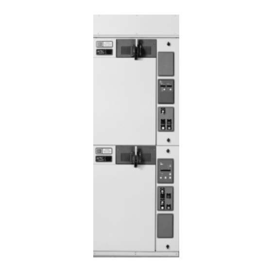
Fig. 1 Ampgard® Motor Controller, 36" Wide
®
EQUIPMENT RATINGS
Induction
100% P.F.
Motor
1750
1500
3000
2500
5000
4000
3800 - 5000 Volts
2250 kVA
2100 kVAR
Interrupting Capacity, 50-60 Hz
(rms) Symmetrical At
Nominal Utilization Voltage
Fuses
Controller
50,000 Amp
200,000 kVA
50,000 Amp
350,000 kVA
50,000 Amp
570,000 kVA
6200 - 7200 Volts
I.B. 48003
Isolating
Switch
Make/Break
Ratings
750 VA
600 VA
600 VA
3000 kVA
2400 kVAR
Advertisement
Table of Contents

Related Manuals for Eaton Cutler-Hammer Ampgard SC9000


Summary of Contents for Eaton Cutler-Hammer Ampgard SC9000
-
Page 1: Controller, Ampgard
Cutler-Hammer I.B. 48003 Instructions for 36" Wide Vacuum-Break Starters Rated 360 Amperes, 7200 Volts, Slide-Out Type DANGER HAZARDOUS VOLTAGE. READ AND UNDERSTAND THIS BOOKLET IN ITS ENTIRETY BEFORE INSTALLING OR OPERATING CONTROLLER. INSTALLATION, ADJUSTMENT, REPAIR AND MAINTENANCE OF THESE CONTROLLERS MUST BE PERFORMED BY QUALIFIED PERSONNEL. -
Page 2: Low-Voltage Components
I.B. 48003 Page 2 THE CONTROLLER (Cont.) While this instruction booklet is dedicated to full-voltage starting, the other applications listed are an expansion of the same principles shown. MEDIUM-VOLTAGE COMPONENTS The flow of current through a vacuum-break controller (starter) can be traced by referring to the upper portion of Figure 4, where the controller is shown in the energized position. -
Page 3: Ampgard Components
I.B. 48003 Page 3 ® Fig. 4 Ampgard Components, Two Starters (Controllers) Shown Effective 11/97... -
Page 4: Door Interference
I.B. 48003 Page 4 LOW-VOLTAGE CONTROL COMPONENTS (Cont.) To energize the primary of the control power transformer, the contactor must be inserted into the enclosure, the power circuit fuses must be installed, and the isolating switch must be closed. For convenience during maintenance, when it may be desirable to energize the contactor or the control circuit, a test-run plug is provided. -
Page 5: Enclosure
I.B. 48003 Page 5 SHORT-CIRCUIT AND OVERLOAD PROTECTION coordinated with the motor characteristics, so that the controller must be used with the motor for which it was Overcurrent protection is provided by the current-limiting designed. Motors with special characteristics often power circuit fuses and by the overload sensor supplied require additional protective relays. -
Page 6: Contactor / Isolating Switch Interlock
I.B. 48003 Page 6 MECHANICAL INTERLOCKS ® Before putting an Ampgard controller into service, become familiar with the mechanical interlocks. Door Interlock. With the isolating switch handle in the HORIZONTAL position, the door to the medium-voltage compartment can be opened. As soon as the door opens, a mechanical interlock becomes effective. -
Page 7: Contactor, General Information
I.B. 48003 Page 7 As a final precaution before touching any of the electrical through zero as it alternates at line frequency. The arc parts of the starter, visually check to make certain that the usually does not survive beyond the first half cycle after shutter is closed, the green and white striped labels are the contacts begin to separate. -
Page 8: Contactor Handling
I.B. 48003 Page 8 THE CONTACTOR (Continued) chassis: a control power transformer with test plug and fuses, instrument-quality potential transformers with The kickout spring is adjustable and occupies the space secondary fuses (when furnished), primary fuses for the above the operating magnet. The kickout spring must be control power and potential transformers, and load side removed before the magnet coil can be changed if that fuse clips for the power circuit fuses. -
Page 9: Contactor Positions
I.B. 48003 Page 9 Fig. 11 Type SJS Contactor Positions Effective 11/97... -
Page 10: Installation
I.B. 48003 Page 10 CONTACTOR HANDLING (Cont.) 7. Loosen the hex-head bolt attaching the clevis at the end of the isolating switch interlock rod to the contactor mechanical interlock sufficiently far to free the clevis and rod. See Figures 7 and 8. Access to this bolt is from the low-voltage compartment. -
Page 11: Disassembly, Key Points
I.B. 48003 Page 11 the enclosure for medium-voltage line and load cables, When there is access space behind the installation, the while low-voltage cables may be conveniently arranged rear panel of the enclosure can be removed to facilitate near the right-hand enclosure wall. See Figure 3. wiring. - Page 12 I.B. 48003 Page 12 Remove the two positioning bolts Remove three power circuit fuses Separate the contactor side of the (A). Free the clevis attached to (B) using the fuse puller (K) control wires from the terminal the mechanical interlock arm. supplied.
- Page 13 I.B. 48003 Page 13 If no vertical bus bars are present Free the isolating switch (H), by Pull the isolating switch forward. and cable is used to connect removing two hex head bolts as CAUTION: It has no latch and will power to the line stabs, loosen shown.
-
Page 14: Start-Up Precautions
I.B. 48003 Page 14 Return the contactor to its Reconnect the clevis attached to Install the three power circuit compartment. Reattach the the mechanical interlock arm. fuses. Make sure each fuse is two positioning bolts. Reconnect the isolating switch fully seated on the bottom fuse auxiliary contact terminal blocks. -
Page 15: Checkout Mechanical
I.B. 48003 Page 15 For Contactor. Be sure that: CAUTION 1. THE FOUR PHASE BARRIERS ARE INSTALLED WHEN PROVIDED. 2. The contactor coil is electrically isolated, to prevent feedback into a control power transformer and a SOME DC HIGH POTENTIAL UNITS, OPERATING AS hazardous situation. -
Page 16: Fuses
I.B. 48003 Page 16 c) Be trained in rendering first aid. d) Be knowledgeable with respect to electrical installa- DANGER tion codes and standards, for example, the National Electrical Code (NEC). OPERATE THE ISOLATING SWITCH ONLY WITH ALL MAINTENANCE PROGRAM DOORS CLOSED AND COMPLETELY LATCHED. -
Page 17: Contactor Maintenance
I.B. 48003 Page 17 CONTACTOR MAINTENANCE All work on this contactor should be done with the main circuit disconnect device open, and using a separate source of control power to operate the magnet. Before applying external control circuit power, make certain that the contactor coil circuit is electrically isolated, to prevent feedback into a control power transformer that could be hazardous. -
Page 18: Coil Changing
I.B. 48003 Page 18 CONTACTOR MAINTENANCE (Continued) TABLE II. COIL PERFORMANCE Contact Wear Allowance Drop-Out-To- Rated Pick-Up-To-Seal Full-Open Contact material vaporizes from the contact faces during Voltage Voltage Coil every interruption and condenses elsewhere inside the bottle. This is normal, and is provided for by overtravel, Above Below Below... -
Page 19: Auxiliary Contacts For Contactor
I.B. 48003 Page 19 If for some reason a coil must be changed, proceed as and used as a lever to put a corrective set into the follows: magnet frame. it should not be necessary to do this unless the contactor has been damaged and it can be 1. -
Page 20: Auxiliary Contacts For Isolating Switch
I.B. 48003 Page 20 CONTACTOR MAINTENANCE (Continued) Auxiliary Contact Adjustment The 0.410 + .010-inch (10.4 + .25-mm) gap shown for the normally-closed Type L63 auxiliary contact in the insert OPERATING ARM picture in the lower portion of Figure 12 is factory set. The 0.410-inch (10.4-mm) gap is important and must be held. -
Page 21: Contactor Connection Diagram
I.B. 48003 Page 21 Fig. 16 Cable and Connection Diagram Effective 11/97... -
Page 22: Isolating Switch Maintenance
I.B. 48003 Page 22 ISOLATING SWITCH MAINTENANCE As a final precaution before touching any of the electrical parts of the starter with the isolating switch removed, visually check to make certain that the shutter is closed, the green and white striped labels are visible, the ground- ing fingers are in contact with the ground bar, and the tips DANGER of the fuse fingers are visible. -
Page 23: Table Of Contents
I.B. 48003 Page 23 INDEX Page Page ® Insulation Level ............17 Ampgard Components ..........3 Auxiliary Contacts for Contactor ......19 Isolating Switch ............ 4, 9 Auxiliary Contacts for Isolating Switch ....20 Isolating Switch / Contactor Interlock ....... 6 Auxiliary Contact Adjustment ......... - Page 24 I.B. 48003 Page 24 Cutler-Hammer 221 Heywood Road Arden, NC 28704 Effective 11/97 Printed in U.S.A./CCI...
Need help?
Do you have a question about the Cutler-Hammer Ampgard SC9000 and is the answer not in the manual?
Questions and answers