Eaton Cutler-Hammer Digitrip RMS 310 Instructions Manual
3-pole and 4-pole trip unit installation and operation with l-frame and mdl-frame series c circuit breakers
Hide thumbs
Also See for Cutler-Hammer Digitrip RMS 310:
- Instruction leaflet (20 pages) ,
- Instruction manual (13 pages)
Table of Contents
Advertisement
Instructions for the Digitrip RMS 310 3-Pole and 4-Pole Trip Unit Installation
and Operation with L-Frame and MDL-Frame Series C Circuit Breakers
Table of Contents
Description
1
..............................................................
1.1
..................................................
2.0
.............................................................
3.0
3.1
3.2
3.3
..................................................................
.............................................................
3.4
3.5
4.0
..................................................................
4.1
.........................................................
4.2
4.3
4.4
.................................................
5.0
..................................................................
General
5.1
5.2
5.3
5.4
5.5
5.6
...................................................................
6.0
6.1
6.2
..........................................................
7.0
..........................................................
8.0
8.1
...................................................
8.2
A
DEATH, SEVERE PERSONAL INJURY, OR
SUBSTANTIAL PROPERTY DAMAGE CAN RESULT
FROM CONTACT WITH ENERGIZED EQUIPMENT. DO
NOT ATTEMPT INSTALL OR PERFORM
MAINTENANCE ON EQUIPMENT WHILE IT IS
ENERGIZED. ALWAYS VERIFY THAT NO VOLTAGE IS
Effective March 2003 Supersedes I.L. 29C615D dated July 1998
Courtesy of NationalSwitchgear.com
...............................................
.....................................
.....................................
..........................
...........
............................................
..............................
.........................................
.................................
.....................................
................................
.................................
...................................
.........................................
...............................................
.......................................
.......................................
............................................
WARNING
PRESENT BEFORE PROCEEDING WITHTHETASK,
AND ALWAYS FOLLOW GENERALLY ACCEPTED
Page
SAFETY PROCEDURES.
1
CUTLER-HAMMER IS NOT LIABLE FORTHE
1
2
MISAPPLICATION OR MISINSTALLATION OF ITS
2
PRODUCTS.
2
The user is cautioned to observe all recommendations,
2
warnings, and cautions relating to the safety of personnel
3
and equipment as well as all general and local health and
3
safety laws, codes, and procedures.
3
The recommendations and information contained herein
.....
5
are based on Cutler-Hammer experience and judgement,
6
but should not be considered to be all-inclusive or cover-
6
ing every application or circumstance which may arise. If
7
any questions arise, contact Cutler-Hammer for further
7
information or instructions.
7
7
7
7
7
7
7
7
8
8
8
....
8
8
9
9
12
12
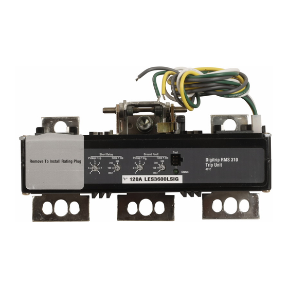
Fig. 1
Digitrip RMS 310 Trip Unit for 3-Pole L-Frame &
MDL Frame Series C Circuit Breaker
12
12
1 .O GENERAL INFORMATION
1.1 Protection
The Digitrip RMS 31 0, illustrated in Figure 1, is an elec-
tronic trip unit that incorporates a microprocessor-based
custom application specific integrated circuit design for
use with Series C L-Frame and MDL Frame Molded Case
Circuit Breakers.
The Digitrip RMS 310 provides true RMS current sensing
for proper correlation with thermal characteristics of
conductors and equipment. Interchangeable rating plugs
I.L. 29C615E
Advertisement
Table of Contents

Subscribe to Our Youtube Channel
Related Manuals for Eaton Cutler-Hammer Digitrip RMS 310


Summary of Contents for Eaton Cutler-Hammer Digitrip RMS 310
-
Page 1: Table Of Contents
I.L. 29C615E Instructions for the Digitrip RMS 310 3-Pole and 4-Pole Trip Unit Installation and Operation with L-Frame and MDL-Frame Series C Circuit Breakers Table of Contents PRESENT BEFORE PROCEEDING WITHTHETASK, AND ALWAYS FOLLOW GENERALLY ACCEPTED Description Page SAFETY PROCEDURES.......... -
Page 2: Ul Listed Devices
I.L. 29C615E Page are provided to establish the continuous current rating of 3 .O INSTAL LATlO N each circuit breaker. 3.1 Preparation (AllTrip Units) The Digitrip RMS 310 Trip Unit is completely self-con- The installation procedure consists of inspecting and tained and when the circuit breaker is closed, requires no installing the trip unit and rating plug. -
Page 3: Ground Faulttrip Unit Installation
I.L. 29C615E Page 3 3.3 Ground FaultTrip Unit Installation 3.3.1 General Ground fault trip units are supplied from the factory with a wire harness with pigtail lead connections for a neutral current sensor (white and grey wires) and a ground fault alarm relay (yellow and green wires). - Page 4 I.L. 29C615E Page 4 Fig. 5 SOURCE - COVER SCREWS LOAD shown Open'' Fig. Fig. 7a MDL Trip Unit Installation Effective March 2003 Courtesy of NationalSwitchgear.com...
-
Page 5: 3-Pole (Non-Ground Fault) Trip Unit Installation
I.L. 29C615E Page Position trip unit in base. Make sure latch bracket pin is properly seated in slots in side plates (see Fig. 8). If necessary, move latch toward load end of circuit breaker to seat trip unit. Screw in and tighten three trip unit retaining screws CAUTION DO NOT EXCEED ATORQUE OF 12 LB-FT (16.27 N.m). -
Page 6: Final Installation Instructions (All Trip Units)
I.L. 29C615E Page 6 For an MDL-frame, also screw in and torque the load end until the arrow points to ENGAGED. If an adjustable rating screws to 6-8 Ib-ft. (8.14-10.85 N.m.) plug is used, four continuous current settings are possible. Set the switch marked A, B, C, D to the current rating 3.5 Final Installation Instructions (All Trip Units) desired. -
Page 7: General
I.L. 29C615E Page 5.0 PROTECTION SETTINGS 5.1 General For ambient conditions above 40°C and where the Prior to placing any circuit breaker in operation, each trip maximum ampere rating plug has been installed, derating unit protection setting must be set to the values specified of the circuit breaker frame should be considered to avoid by the engineer responsible for the installation. -
Page 8: Ground Fault Time Settings
I.L. 29C615E Page 8 by setting Short Delay Time to "I" (Instantaneous.) Short I setting gives a trip response with no intentional delay Delay Pickup (see paragraph 5.2) then becomes Instanta- (Instantaneous). This option is available on Catalog Nos. neous Pickup. LES3xxxLSG, -LSIG, MES3xxxLSG, and -LSIG 5.5 Ground Fault Pick-Up Setting 6.0 TESTING... -
Page 9: Standards Requirements
I.L. 29C615E Page Rating Plug Setting (Amperes) See Fig. 2-7 and Fig. Continuation of Short Time Instantaneous Portions of Curves Time Ms Current Current Fig. 12-3 Ground Fault Trip Current, and Ground Fault Trip Fig. 13 Optional Adjustable Ampere Setting Rating Time Adjustments and Curve Details Plug Used in L ES Trip Unit provided with the equipment. - Page 10 I.L. 29C615E Page 10 voltage Source Source Load Current-Lim iring Current Limiting Load Resistor (if required1 (if required) Fig. 14-1 Connections for Ground Fault Trip Test Fig. 14-2 Connections for Ground Fault No-Trip Test, with a Four- Wire System Voltage Source Fig.
- Page 11 I.L. 29C615E Page 11 GROUND FAULT TEST RECORD FORM Ground Fault Test Record should be Retained by Those in Charge of the Building's Electrical Installation in order to be available to the Authority having Jurisdiction. Results Tested By: Circuit Test Date Breaker Number Fig.
-
Page 12: Rating Plug
I.L. 29C615E Page 12 If the system is a 4-wire system with a neutral current For adjustable rating plugs (Table 1 -2), the primary sensor, apply the same current as described above current carrying conductors used with the breaker must through one phase of the breaker, returning through the be sized to correspond with the maximum setting of the neutral sensor, as shown in Fig. - Page 13 I.L. 29C615E Page 13 Table 1-1. Digitrip RMS Trip Unit Types Trip Unit Functions Digitrip RMS 310 Trip Unit Type Catalog Numbers LES3600LS LES3600LSI LES4600LSP LES4600LS LES3600LSG LES3600LSIG LES4600LSI LES4600LSIP LES3630LS LES3630LSI LES4630LS LES4630LSE LES4630LSIE LES4630LSP LES4630LSIP LES4630LSI LES4800LS MES3800LS MES3800LSI MES3800LSIG MES3800LSG...
- Page 14 I.L. 29C615E Page 14 Table 1-2. Digitrip RMS Trip Unit Function and Rating Settings Trip Function Rating/ S etting Description Ampere Rating Fixed rating plugs available Fixed at 100% Trip Unit Fixed Rating Plugs 630A Adjustable Long Delay Pick-up Trip Unit Ampere Rating Adjustable Rating Plugs 630A...
Need help?
Do you have a question about the Cutler-Hammer Digitrip RMS 310 and is the answer not in the manual?
Questions and answers
How does a person determine to use a digitrip 310 + when looking at a Eaton breaker example HFDE 65k 160 amps