Table of Contents
Advertisement
Quick Links
Advertisement
Table of Contents

Related Manuals for Blackbox EMS1G24F


Summary of Contents for Blackbox EMS1G24F
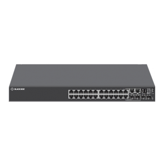
- Page 1 HARDWARE INSTALLATION GUIDE EMS1G24F 24-PORT 1G IP NETWORK SWITCH 24/7 TECHNICAL SUPPORT AT 1.877.877.2269 OR VISIT BLACKBOX.COM LINK 23 ACT Stack No. LINK SFP+ COMBO PORTS...
-
Page 2: Table Of Contents
5.4 Connecting the Stacking Ports (Optional) ............................21 5.5 Ground Cable ......................................22 5.6 Optics Installation ....................................23 5.7 Optics Removal.......................................23 5.8 Powering Up the Switch ..................................23 6. POWER SUPPLIES ..................................24 6.1 Components ......................................24 6.2 AC Power Supply Installation ................................25 6.3 AC Power Supply Replacement ................................26 1.877.877.2269 BLACKBOX.COM... - Page 3 A.6 Safety Certifications and Compliance Agency Certifications ......................38 A.7 Electromagnetic Compatibility ................................38 A.7.1 Emissions ...........................................38 A.7.2 Immunity ..........................................39 A.8 Product Recycling and Disposal (WEEE) .............................39 APPENDIX B. DISCLAIMER/TRADEMARKS ..........................40 B.1 Disclaimer .......................................40 B.2 Trademarks Used in this Manual ................................40 1.877.877.2269 BLACKBOX.COM...
-
Page 4: Safety Instructions
WARNING: This equipment contains optical transceivers, which comply with the limits of Class 1 laser radiation. CLASS 1 LASER PRODUCT WARNING: When no cable is connected, visible and invisible laser radiation may be emitted from the aperture of the optical transceiver ports. Avoid exposure to laser radiation. Do not stare into open apertures. 1.877.877.2269 BLACKBOX.COM... -
Page 5: Specifications
TECHNICAL SUPPORT 1.877.877.2269 24-PORT 1G NETWORK SWITCH (EMS1G24F) SPECIFICATIONS APPROVALS Environmental Compliances: Japan: VCCI V3/2009 Class A; USA: FCC CFR 47 Part 15, Subpart B:2009, Class A; RoHS EMI Certifications: Australia/New Zealand: AS/NZS CISPR 32: Class A; Canada: ICES-003, Issue-4, Class A; Europe: EN 55032: 2015+A1:2007 (CISPR 32);... -
Page 6: Overview
SUPPORT 1.877.877.2269 2.1 INTRODUCTION The EMS1G24F is a low-cost switch for 1 Gbps fiber links to servers, 1G copper combo ports for campus network endpoints, and 10 Gbps fiber uplinks to core/aggregation switches. 2.2 FEATURES Š Twenty-four 100BASE-FX/1000BASE-X SFP ports Š... -
Page 7: Compatible Sfp Modules
SFP+ - 10-Gb, Extended Diagnostics, 850-nm Multimode Fiber, LC 300 m LSP442 SFP+ - 10-Gb, Extended Diagnostics, 1310-nm Single-mode Fiber, LC 10 km LSP443 SFP+, 10GBASE-T, RJ-45 30 m NOTE: Black Box switches will also support generic SFP+ modules. 1.877.877.2269 BLACKBOX.COM... -
Page 8: Hardware Description
10G SFP+ modules (not included) install here (2) 1G copper combo ports Dual-media ports, each consisting of (1) 10-/100-/1000-Mbps RJ-45 and (1) 100/1000 SFP (24) 1G SFP ports 1G SFP modules (not included) install here to link to 100BASE-FX/1000BASE-X devices 1.877.877.2269 BLACKBOX.COM... -
Page 9: Back Panel
2-port 10GbE SFP+ hot swappable uplink module (1) fan tray Provides proper ventilation Full-duplex high-availability stacking architecture that allows (2) mini-SAS stacking ports management of up to 12 switches from a single IP address (1) power supply Provides redundant power 1.877.877.2269 BLACKBOX.COM... -
Page 10: Led Indicators
1.877.877.2269 2.6.3 LED INDICATORS The EMS1G24F includes LED displays on the I/O side of the switch. This section describes open networking installation environment (ONIE) LED behaviors. Some LED behaviors may change after you install your software. The following EMS1G24F switch LED behavior is seen during ONIE operations. - Page 11 • Solid green — Link on 1000 Mbps speed • Solid amber — Link on 100 Mbps speed ACT (Data transmission): (1) Combo SFP (1G) • Off — No link port ACT LED • Blinking green — Activity 1.877.877.2269 BLACKBOX.COM...
-
Page 12: Preparing The Site
Ground the equipment rack to the same ground point the power service in your area uses. The ground path must be permanent. 3.4 SWITCH GROUND Black Box recommends you ground your switch. Use the EMS1G24F in a common bond network (CBN). Connect the grounding cables as described in Install the Switch. -
Page 13: Fans And Airflow
Š For proper ventilation, position the EMS1G24F in an equipment rack or cabinet with a minimum of 5 inches (12.7 cm) of clearance around the exhaust vents. When you install two EMS1G24F switches near each other, to permit proper airflow, position the two chassis at least 5 inches (12.7 cm) apart. -
Page 14: Nebs Compliance
OSP wiring. WARNING: If you install and connect the EMS1G24F switch to a commercial AC power source, you must connect the switch to an external special protection device (SPD). -
Page 15: Installing The Switch
Š Reliable earthing—Maintain reliable earthing of rack-mounted equipment. Pay particular attention to the supply connections other Š than the direct connections to the branch circuit, for example: use of power strips. Š Do not mount the equipment with the rear panel facing in the downward position. Š 1.877.877.2269 BLACKBOX.COM... -
Page 16: Rails System Installation
5.2.2 RAILS SYSTEM INSTALLATION The rackmounting system is provided to easily configure your rack for installation of your EMS1G24F switch. You can install the rail system using the 1U tool-less method or one of three 1U tooled methods—two-post flush mount, two-post center mount or four-post threaded. - Page 17 2. Attach one rail to the front post flange with two user-supplied screws, item 2. 3. Slide the plunger bracket forward against the vertical post and secure the plunger bracket to the post flange with two user-supplied screws, item 3. 4. Repeat this procedure for the second rail. 1.877.877.2269 BLACKBOX.COM...
- Page 18 1. Slide the plunger bracket rearward until it clicks into place and secure the bracket to the front post flange with two user-supplied screws, item 1. FIGURE 5-3. TWO-POST CENTER-MOUNT CONFIGURATION 2. Slide the back bracket towards the post. Secure it to the post flange with two user-supplied screws, to item 2. 3. Repeat this procedure for the second rail. 1.877.877.2269 BLACKBOX.COM...
- Page 19 To remove the two screws from each flange ear and remove each casting, use a Torx driver, item 1. Retain the castings for future rack requirements. FIGURE 5-4. FOUR-POST THREADED CONFIGURATION 2. For each rail, attach the front and rear flanges to the post flanges with two user-supplied screws at each end, item 2. 1.877.877.2269 BLACKBOX.COM...
-
Page 20: Switch Installation
1U FRONT-RACK INSTALLATION Configure the rails that are attached to the switch. 1. Attach the inner chassis members switch rails to the EMS1G24F switch. Item 3 shows the detail for the front standoff with the locking tab. FIGURE 5-5. SWITCH RAILS ATTACHMENT 2. -
Page 21: Connecting The Stacking Ports (Optional)
When a master failure is detected, the standby unit initializes the control plane and enables all other stack units with the current configuration. The standby unit maintains a synchronized copy of the running configuration for the stack. 1.877.877.2269 BLACKBOX.COM... -
Page 22: Ground Cable
3. Attach the one-hole lug to the chassis using the supplied 10–32 screw with the captive internal tooth lock washer. Torque the screw to 20 in-lbs. 4. Attach the other end of the ground cable to a suitable ground point. The rack installation ears are not a suitable grounding point. 1.877.877.2269 BLACKBOX.COM... -
Page 23: Optics Installation
1.877.877.2269 5.6 OPTICS INSTALLATION The EMS1G24F has (24) 1G SFP optical ports and (2) 10G SFP+ optical uplink ports. Compatible SFP+ modules are listed in Section 2.5. CAUTION: ESD damage can occur if components are mishandled. Always wear an ESD-preventive wrist or heel ground strap when handling the EMS1G24F and its components. -
Page 24: Power Supplies
• AC power supply with integrated fan The EMS1G24F switch includes an AC power supply with airflow from the I/O side to the PSU side. Two PSUs are required for full redundancy, but the switch can operate with a single PSU. -
Page 25: Ac Power Supply Installation
5. If you have a redundant PSU, repeat steps 1 through 4 above using the second PSU slot on the switch. NOTE: The switch powers up when you connect the cables between the power supply and the power source. 1.877.877.2269 BLACKBOX.COM... -
Page 26: Ac Power Supply Replacement
NOTE: If a PSU fails, you must replace the entire unit. There are no field serviceable components in the PSU. To request a hardware replacement, contact Black Box Technical Support at 877-877-2269 or info@blackbox.com NOTE: If you use a single PSU, install a blank plate in the other PSU slot. If you are only using one power supply, we recommend installing the power supply in the first slot (PSU1) and installing a blank plate in the second slot (PSU2). -
Page 27: Fans
CAUTION: Check the fans at six-month intervals and replace them as necessary. Regularly monitor the speeds of the fans to accurately determine replacement intervals. 7.1 COMPONENTS The following are the EMS1G24F fan components. • EMS1G24F Fan module 1.877.877.2269 BLACKBOX.COM... -
Page 28: Fan Module Installation
1. Slide the fan module out of the bay. 2. Slide the replacement module into the bay. 7.4 AFTER INSTALLING THE SWITCH After you have securely installed and powered on the switch, to configure your switch, see your ONIE-compatible operating system documentation. 1.877.877.2269 BLACKBOX.COM... -
Page 29: Installing The Sofware
2. Connect the other end of the cable to the DTE terminal server. 3. Set the default terminal settings as follows. Š 9600 baud rate Š Š No parity Š Š Eight data bits Š Š One stop bit Š Š No flow control Š 1.877.877.2269 BLACKBOX.COM... -
Page 30: Accessing The Rj-45 Console Port With A Db9 Adapter
Layer 2 mode. 1. Enable the interface. INTERFACE mode no shutdown 2. Place the interface in Layer 2 (switching) mode. INTERFACE mode switchport To view the interfaces in Layer 2 mode, use the show interfaces switchport command in EXEC mode. 1.877.877.2269 BLACKBOX.COM... -
Page 31: Configuring A Host Name
Define a path from the switch to the network from which you will remotely access the system. Management routes are separate from IP routes; they manage the system through the management port. • Configure a management route to the network from which you will access the system. CONFIGURATION mode management route ip-address/mask gateway 1.877.877.2269 BLACKBOX.COM... -
Page 32: Configuring The Username And Password
To tag frames leaving an interface in Layer 2 mode, assign that interface as tagged to a port-based VLAN to tag it with that VLAN To move untagged interfaces from the default VLAN to another VLAN, use the untagged command. 1.877.877.2269 BLACKBOX.COM... -
Page 33: Assigning An Ip Address To A Vlan
Configure an IP address and mask on the interface. 8.15 CONNECTING THE SYSTEM TO THE NETWORK After you have completed the hardware installation and software configuration for the system, connect to your company network by following your company’s cabling requirements. 1.877.877.2269 BLACKBOX.COM... -
Page 34: Troubleshooting
If you determine that your switch is malfunctioning, do not attempt to alter or repair the unit. It contains no user-serviceable parts. Contact Black Box Technical Support at 877-877-2269 or info@blackbox.com. Before you do, make a record of the history of the problem. We will be able to provide more efficient and accurate assistance if you have a complete description, including: Š... -
Page 35: Appendix A. Regulatory Information
This device complies with Part 15 of the FCC Rules. Operation is subject to the following two conditions: (1) this device may not cause harmful interference, and (2) this device must accept any interference received, including interference that may cause undesired operation. 1.877.877.2269 BLACKBOX.COM... -
Page 36: Nom Statement
B: Objectos han caído o líquido ha sido derramado dentro del aparato; o C: El aparato ha sido expuesto a la lluvia; o D: El aparato parece no operar normalmente o muestra un cambio en su desempeño; o E: El aparato ha sido tirado o su cubierta ha sido dañada. 1.877.877.2269 BLACKBOX.COM... -
Page 37: European Union Emc Directive Conformance Statement
Equipment (VCCI). If this equipment is used in a domestic environment, radio disturbance may arise. When such trouble occurs, the user may be required to take corrective actions. WARNING: Use the AC power cords with Black Box equipment only. 1.877.877.2269 BLACKBOX.COM... -
Page 38: Korean Certification Of Compliance
Š Australia/New Zealand: AS/NZS CISPR 22:2009, Class A Š Š Canada: ICES-003, Issue-4, Class A Š Š Europe: EN55022 2006 (CISPR 22: 2006), Class A Š Š Japan: VCCI V-3/2011.04 Class A Š Š USA: FCC CFR47 Part 15, Subpart B, Class A Š 1.877.877.2269 BLACKBOX.COM... -
Page 39: Immunity
(WEEE). The Directive determines the framework for the return and recycling of used appliances as applicable throughout the European Union. This label is applied to various products to indicate that the product is not to be thrown away, but rather reclaimed upon end of life per this Directive. 1.877.877.2269 BLACKBOX.COM... -
Page 40: Appendix B. Disclaimer/Trademarks
B.2 TRADEMARKS USED IN THIS MANUAL Black Box and the Black Box logo type and mark are registered trademarks of Black Box Corporation. Any other trademarks mentioned in this manual are acknowledged to be the property of the trademark owners. 1.877.877.2269 BLACKBOX.COM... - Page 41 NEED HELP? LEAVE THE TECH TO US LIVE 24/7 NOTES TECHNICAL SUPPORT 1.877.877.2269 __________________________________________________________________________________________________ __________________________________________________________________________________________________ __________________________________________________________________________________________________ __________________________________________________________________________________________________ __________________________________________________________________________________________________ __________________________________________________________________________________________________ _________________________________________________________________________________________________ __________________________________________________________________________________________________ __________________________________________________________________________________________________\ __________________________________________________________________________________________________ __________________________________________________________________________________________________ __________________________________________________________________________________________________ __________________________________________________________________________________________________ _________________________________________________________________________________________________ __________________________________________________________________________________________________ __________________________________________________________________________________________________ __________________________________________________________________________________________________ 1.877.877.2269 BLACKBOX.COM...
- Page 42 NEED HELP? LEAVE THE TECH TO US LIVE 24/7 NOTES TECHNICAL SUPPORT 1.877.877.2269 __________________________________________________________________________________________________ __________________________________________________________________________________________________ __________________________________________________________________________________________________ __________________________________________________________________________________________________ __________________________________________________________________________________________________ __________________________________________________________________________________________________ _________________________________________________________________________________________________ __________________________________________________________________________________________________ __________________________________________________________________________________________________\ __________________________________________________________________________________________________ __________________________________________________________________________________________________ __________________________________________________________________________________________________ __________________________________________________________________________________________________ _________________________________________________________________________________________________ __________________________________________________ 1.877.877.2269 BLACKBOX.COM...
- Page 43 NEED HELP? LEAVE THE TECH TO US LIVE 24/7 NOTES TECHNICAL SUPPORT 1.877.877.2269 __________________________________________________________________________________________________ __________________________________________________________________________________________________ __________________________________________________________________________________________________ __________________________________________________________________________________________________ __________________________________________________________________________________________________ __________________________________________________________________________________________________ _________________________________________________________________________________________________ __________________________________________________________________________________________________ __________________________________________________________________________________________________\ __________________________________________________________________________________________________ __________________________________________________________________________________________________ __________________________________________________________________________________________________ __________________________________________________________________________________________________ _________________________________________________________________________________________________ __________________________________________________________________________________________________ __________________________________________________________________________________________________ __________________________________________________________________________________________________ ________________________________________________ 1.877.877.2269 BLACKBOX.COM...
- Page 44 NEED HELP? LEAVE THE TECH TO US LIVE 24/7 TECHNICAL SUPPORT 1.877.877.2269 © COPYRIGHT 2020. BLACK BOX CORPORATION. ALL RIGHTS RESERVED. EMS1G24F_INSTALL_REV1.PDF...
Need help?
Do you have a question about the EMS1G24F and is the answer not in the manual?
Questions and answers