Table of Contents
Advertisement
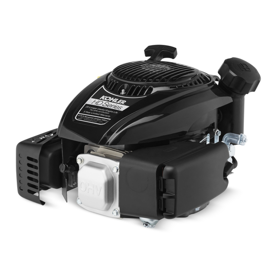
HD675, HD775
Service Manual
IMPORTANT:
Read all safety precautions and instructions carefully before operating equipment. Refer to operating
instruction of equipment that this engine powers.
Ensure engine is stopped and level before performing any maintenance or service.
2
Safety
3
Maintenance
5
Specifi cations
12
Tools and Aids
15
Troubleshooting
20
Air Cleaner/Intake
21
Fuel System
28
Governor System
30
Lubrication System
32
Electrical System
38
Starter System
42
Disassembly/Inspection and Service
55
Reassembly
14 690 10 Rev. --
KohlerEngines.com
1
Advertisement
Table of Contents

Related Manuals for Kohler HD Series


Summary of Contents for Kohler HD Series
- Page 1 HD675, HD775 Service Manual IMPORTANT: Read all safety precautions and instructions carefully before operating equipment. Refer to operating instruction of equipment that this engine powers. Ensure engine is stopped and level before performing any maintenance or service. Safety Maintenance Specifi cations Tools and Aids Troubleshooting Air Cleaner/Intake...
-
Page 2: Safety Precautions
Safety SAFETY PRECAUTIONS WARNING: A hazard that could result in death, serious injury, or substantial property damage. CAUTION: A hazard that could result in minor personal injury or property damage. NOTE: is used to notify people of important installation, operation, or maintenance information. CAUTION WARNING WARNING... -
Page 3: Maintenance Instructions
Perform these procedures more frequently under severe, dusty, dirty conditions. REPAIRS/SERVICE PARTS Kohler genuine service parts can be purchased from Kohler authorized dealers. To fi nd a local Kohler authorized dealer visit KohlerEngines.com or call 1-800-544-2444 (U.S. and Canada). 14 690 10 Rev. --... -
Page 4: Oil Recommendations
OIL RECOMMENDATIONS STORAGE If engine will be out of service for 2 months or more We recommend use of Kohler oils for best performance. follow procedure below. Other high-quality detergent oils (including synthetic) of API (American Petroleum Institute) service class SJ 1. -
Page 5: Specifications
Exceeding maximum angle of operation may cause engine damage from insuffi cient lubrication. Any and all horsepower (hp) references by Kohler are Certifi ed Power Ratings and per SAE J1940 & J1995 hp standards. Details on Certifi ed Power Ratings can be found at KohlerEngines.com. - Page 6 Specifi cations TORQUE SEQUENCES HD675 HD775 HD675 Oil Pan Fasteners HD775 Oil Pan Fasteners Valve Cover Fasteners TORQUE SPECIFICATIONS HD675 HD775 Air Cleaner Base Stud Fastener 8 N·m (71 in. lb.) Crankcase Fastener 8 N·m (71 in. lb.) Blower Housing Stud 10 N·m (89 in.
- Page 7 Specifi cations TORQUE SPECIFICATIONS HD675 HD775 Brake (if equipped) Mounting Fastener 9.5 N·m (84 in. lb.) Breather Cover Fastener 10 N·m (89 in. lb.) Carburetor Stud Fastener 8 N·m (71 in. lb.) Stud 5 N·m (44 in. lb.) Auto Choke Arm Assembly Nut (if equipped) 8.5 N·m (75 in.
-
Page 8: Clearance Specifications
Specifi cations TORQUE SPECIFICATIONS HD675 HD775 Muffl er Exhaust Stud 5.0 N·m (44 in. lb.) Lock Nut 9.5 N·m (84 in. lb.) Shoulder Screw 9.5 N·m (84 in. lb.) Oil Pan (torque sequence on page 6 ) Oil Drain Plug 13.6 N·m (120 in. - Page 9 Specifi cations CLEARANCE SPECIFICATIONS HD675 HD775 Crankshaft End Play (free) 0.427/1.298 mm (0.0168/0.05110 in.) Bore in Oil Pan I.D. 27.050/27.071 mm (1.06496/1.06578 in.) Bore in Oil Pan Running Clearance 0.008/0.121 mm (0.0031/0.00476 in.) Bearing (fl ywheel) Journal O.D. 25.005/25.019 mm 24.975/24.989 mm (0.9844/0.9850 in.) (0.9832/0.9838 in.)
- Page 10 Specifi cations CLEARANCE SPECIFICATIONS HD675 HD775 Piston, Piston Rings, and Piston Pin Pin Bore I.D. 13.002/13.008 mm 18.000/18.008 mm (0.5118/0.5121 in.) (0.7086/0.7089 in.) Pin O.D. 12.990/12.996 mm 17.990/17.996 mm (0.5114/0.5116 in.) (0.7082/0.7085 in.) Top and Center Compression Ring Side Clearance New Bore 0.001/0.020 mm (0.00004/0.00080 in.) Top and Center Compression Ring End Gap...
-
Page 11: General Torque Values
Specifi cations GENERAL TORQUE VALUES English Fastener Torque Recommendations for Standard Applications Bolts, Screws, Nuts and Fasteners Assembled Into Cast Iron or Steel Grade 2 or 5 Fasteners Into Aluminum Size Grade 2 Grade 5 Grade 8 Tightening Torque: N·m (in. lb.) ± 20% 8-32 2.3 (20) 2.8 (25) -
Page 12: Tools And Aids
Shrader Valve Adapter Hose DTI-037 Wire Probe Set (2 pieces regular wire with clip; 1 piece fused wire) DTI-031 Hose Removal Tool, Dual Size/End (also sold as individual Kohler tool) DTI-033 K-Line Adapter Jumper Lead Wiring Harness Kohler 25 176 23-S... - Page 13 For reaming worn valve guides to accept replacement oversize valves. Can be used in low-speed drill press or with handle below for hand reaming. Reamer Handle Design Technology Inc. For hand reaming using Kohler 25 455 12-S reamer. DTI-K830 AIDS Description Source/Part No.
- Page 14 Tools and Aids FLYWHEEL HOLDING TOOL ROCKER ARM/CRANKSHAFT TOOL A fl ywheel holding tool can be made out of an old junk A spanner wrench to lift rocker arms or turn crankshaft fl ywheel ring gear and used in place of a strap wrench. may be made out of an old junk connecting rod.
-
Page 15: Troubleshooting Guide
Troubleshooting TROUBLESHOOTING GUIDE When troubles occur, be sure to check simple causes which, at fi rst, may seem too obvious to be considered. For example, a starting problem could be caused by an empty fuel tank. Some general common causes of engine troubles are listed below and vary by engine specifi cation. Use these to locate causing factors. - Page 16 Troubleshooting CLEANING ENGINE Engine Uses Excessive Amount of Oil ● Loose or improperly torqued fasteners. WARNING ● Blown head gasket/overheated. Cleaning Solvents can cause severe injury or ● Breather reed broken. death. ● Clogged, broken, or inoperative crankcase breather. Use only in well ventilated areas away from ●...
-
Page 17: Crankcase Vacuum Test
Troubleshooting CRANKCASE VACUUM TEST WARNING WARNING Carbon Monoxide can cause severe nausea, Rotating Parts can cause severe injury. fainting or death. Stay away while engine is in operation. Avoid inhaling exhaust fumes. Never run engine indoors or in enclosed spaces. Keep hands, feet, hair, and clothing away from all Engine exhaust gases contain poisonous carbon moving parts to prevent injury. -
Page 18: Compression Test
Troubleshooting COMPRESSION TEST These engines are equipped with an automatic compression release (ACR) mechanism. It is diffi cult to obtain an accurate compression reading because of ACR mechanism. As an alternative, use cylinder leakdown test described below. CYLINDER LEAKDOWN TEST A cylinder leakdown test can be a valuable alternative to a compression test. - Page 19 Troubleshooting Test Pressure Chart for Dual Gauge Tool Left Gauge Regulated Pressure Selection Right Gauge Reading in PSI 80 PSI Recommended for engines over 200 cc or those exhibiting high leakage at 35 PSI setting. 35 PSI Recommended for single cylinder 31.5 24.5 17.5...
-
Page 20: Air Cleaner/Intake
Air Cleaner/Intake AIR CLEANER BREATHER TUBE These systems are CARB/EPA certifi ed and components Make sure both ends of breather tube are properly should not be altered or modifi ed in any way. connected. Air Cleaner Components AIR COOLING WARNING Hot Parts can cause severe burns. -
Page 21: Fuel System
2. Inspect both in-nipple fuel fi lters (located at fuel tank Low permeation fuel line must be installed on carbureted outlet fi tting and tee fi tting) for dirt/debris. Clean/ Kohler Co. engines to maintain EPA and CARB replace as required. regulatory compliance. -
Page 22: Fuel System Tests
Fuel System FUEL SYSTEM TESTS When engine starts hard, or turns over but will not start, fuel system might be causing problems. Test fuel system by performing following tests. 1. Check for fuel in combustion chamber. a. Disconnect and ground spark plug lead. b. - Page 23 Fuel System CARBURETOR Gasoline is extremely fl ammable and its vapors can WARNING explode if ignited. Store gasoline only in approved Explosive Fuel can cause fi res and severe containers, in well ventilated, unoccupied buildings, away burns. from sparks or fl ames. Spilled fuel could ignite if it comes in contact with hot parts or sparks from ignition.
- Page 24 Fuel System Troubleshooting-Carburetor Related Causes Condition Possible Cause Conclusion Engine starts hard, runs rough, or Low idle fuel mixture (some models)/ Adjust idle speed screw or clean stalls at idle speed. speed improperly adjusted. carburetor. Engine runs rich (indicated by black, Clogged air cleaner.
- Page 25 4000 ft. (1219 meters) or above, a high altitude carburetor kit is required. To obtain high altitude carburetor kit information or to fi nd a Kohler authorized Accidental Starts can cause severe injury or dealer, visit KohlerEngines.com or call 1-800-544-2444 death.
- Page 26 Fuel System 5. Note position of choke plate. Attach a vacuum pump Cover, Element, and Breather Cover to vacuum hose. Choke plate should open 1/2 to 3/4 under vacuum and with a minimum of 15" of water. If diaphragm assembly is unable to open choke plate, check hose for cracks, leaks, or restrictions.
- Page 27 Fuel System When engine is cold, spring around base of choke shaft Auto Choke Components - Link Design holds choke closed for starting. When engine starts, governor closes throttle from wide open to set governor speed. As throttle closes, link between throttle and choke operates choke to a slightly open position.
-
Page 28: Governor System
Governor System GOVERNOR Governor Components Brake Spring (if Brake Lever (if Fixed Speed Control Governor Cross Shaft equipped) equipped) Bracket E High Speed Adjustment Governor Lever Screw Variable Speed Control Governor Spring Linkage Spring Linkage Lever KohlerEngines.com 14 690 10 Rev. --... - Page 29 Governor System Intermediate Control High Speed Adjusting Control Spring Regulating Pin Lever Screw Governor Shaft Flyweight(s) Governor Gear Governor Gear Shaft Retainer Governed speed setting is determined by position of throttle control. It can be variable or constant, depending on engine application.
-
Page 30: Lubrication System
Lubrication System These engines use a splash lubrication system, supplying necessary lubrication to crankshaft, camshaft, connecting rod, and valve train components. Lubrication Components 1/4 Turn Cap Threaded Cap Air Cleaner Crankcase Plugs Oil Fill Cap/ Dipstick OIL RECOMMENDATIONS CHANGE OIL Refer to Maintenance. - Page 31 Lubrication System Crankcase plug 1. Disable engine by disconnecting spark plug. 2. Clean area around oil fi ll cap/dipstick. Remove oil fi ll cap/dipstick. 3. Remove crankcase plug on bottom of engine; drain oil into appropriate container. 4. Apply thread sealant around three full threads of drain plug;...
-
Page 32: Electrical System
Electrical System SPARK PLUGS Inspection Inspect each spark plug as it is removed from cylinder CAUTION head. Deposits on tip are an indication of general Electrical Shock can cause injury. condition of piston rings, valves, and carburetor. Do not touch wires while engine is running. Normal and fouled plugs are shown in following photos: Normal Spark Plug Component and Details... -
Page 33: Electronic Ignition System
Electrical System Carbon Fouled ELECTRONIC IGNITION SYSTEM Inductive Discharge Ignition System Soft, sooty, black deposits indicate incomplete combustion caused by a restricted air cleaner, over rich carburetion, weak ignition, or poor compression. Overheated Stop/Kill Switch Flywheel Magnet Ignition Module Lamination Kill Terminal Spark Plug Spark Plug Boot... - Page 34 Electrical System Electronic Ignition System Tests (Retractable Start) Test Ignition System Remove spark plug. Check condition of spark plug. Make sure gap is set to 0.76 mm (0.030 in.). Install spark plug and torque to 27 N·m (20 ft. lb.). Condition Possible Cause Conclusion...
- Page 35 Electrical System Electronic Ignition System Tests (Electric Start) 1. Disconnect cap from spark plug and attach it to 3. Set an ohmmeter to Rx1K or Rx10K scale and zero. terminal end of spark tester. Attach tester spring clip Connect one ohmmeter lead to module kill lead tab to a good ground, not to spark plug.
- Page 36 Electrical System Rectifi ed Only (non-regulated) Systems (if equipped) Some engines are equipped with a rectifi ed (in-line diode) only, non-regulated 1 amp charging system. Diode (rectifi er) is a sealed in-line wiring jumper between stator and a battery (B+) connection (OEM location). Jumper features male/female bullet connectors and can only be installed one way.
- Page 37 Electrical System 1 Amp Battery Charging System NOTE: Zero ohmmeters on each scale to ensure accurate readings. Voltage tests should be made with engine running at high speed - no load. Battery must be fully charged. If low, recharge or replace battery as necessary.
-
Page 38: Starter System
Starter System NOTE: Do not crank engine continuously for more than 10 seconds. Allow a 60 second cool down period between starting attempts. Failure to follow these guidelines can burn out starter motor. NOTE: If engine develops suffi cient speed to disengage starter but does not keep running (a false start), engine rotation must be allowed to come to a complete stop before attempting to restart engine. - Page 39 Starter System 2. Use a known, good, fully-charged battery and Electric Starting System Tests (With Brake jumper cables to test starter motor. Be sure drive Assembly) unit is in neutral, blade is off (if equipped with a NOTE: Battery must be fully charged. If low, recharge or blade brake clutch (BBC) assembly), and/or replace battery as necessary.
-
Page 40: Retractable Starters
Starter System RETRACTABLE STARTERS Remove Starter NOTE: Whenever possible, an impact wrench should be WARNING used to loosen nuts securing retractable starter. Uncoiling Spring can cause severe injury. 1. Remove nuts securing starter to blower housing. Wear safety goggles or face protection when 2. - Page 41 Starter System Pawls (dogs) Replacement 1. Install a clamp to hold pulley in starter housing and prevent it from rotating. 2. Unscrew center screw and lift off drive plate. 3. Note positions of pawls and pawl springs before removing. Remove parts from pulley. 4.
-
Page 42: Disassembly/Inspection And Service
Disassembly/Inspection and Service WARNING Before working on engine or equipment, disable engine as Accidental Starts can cause severe injury or follows: 1) Disconnect spark plug lead(s). 2) Disconnect death. negative (–) battery cable from battery. Disconnect and ground spark plug lead(s) before servicing. - Page 43 Disassembly/Inspection and Service Clean all parts thoroughly as engine is disassembled. Drain Oil From Crankcase Plug (if accessible) Only clean parts can be accurately inspected and gauged for wear or damage. There are many commercially available cleaners that will quickly remove grease, oil, and grime from engine parts.
- Page 44 Disassembly/Inspection and Service 1. Loosen knob and remove air cleaner cover. Remove Air Cleaner Assembly 2. Remove precleaner and paper element. 3. Remove nuts securing air cleaner base to carburetor studs and screw securing base to crankcase. 4. Using Hose Removal Tool (See Tools and Aids), carefully remove breather hose from air cleaner base.
- Page 45 Disassembly/Inspection and Service 3. Remove nuts securing fuel pump bracket to engine. Remove Carburetor with Auto Choke (if equipped) Remove fuel pump bracket, fuel pump, fuel lines from engine. On engines equipped with a fuel pump, top nut that secure fuel pump bracket also secures speed control assembly bracket to stud in crankcase.
- Page 46 Disassembly/Inspection and Service 4. Disconnect governor linkage and linkage spring from Remove Governor Lever carburetor. Loosen governor lever nut and slide lever off governor 5. Remove carburetor. shaft. 6. Remove nuts securing arm assembly to muffl er. Second nut is located behind arm assembly base Flywheel/Ignition/Fuel Tank Components securing it to top of muffl...
- Page 47 Disassembly/Inspection and Service NOTE: Some engines are built with a one-piece Remove Ignition Module breather fi lter and some are built with a two- 1. Disconnect kill lead from ignition module. piece breather fi lter. Designs are not interchangeable. 2. Remove screw and stud securing ignition module. Mark stud for identifi...
- Page 48 Disassembly/Inspection and Service Cylinder Head Components Valve Cover Jam Nut Rocker Arm Pivot Rocker Arms Push Rod Guide Rocker Arm Stud Push Rod Valve Keeper Plate Valve Spring Intake Valve Seal Spark Plug Baffl e Cylinder Head Valve Dowel Pin Remove Valve Cover Remove Jam Nuts and Rocker Arm Pivots NOTE:...
- Page 49 Disassembly/Inspection and Service Remove Guide Plate Remove Valve Assembly 1. Remove guide plate from rocker studs. NOTE: Only intake valve has a seal. There is no valve seal on exhaust side. 2. Note orientation of guide plate (tabs down) for use during reassembly.
- Page 50 Disassembly/Inspection and Service After cleaning, check flatness of cylinder head and Valve Seat Inserts corresponding top surface of crankcase, using a Hardened steel alloy intake and exhaust valve seat surface plate or precision straight edge and feeler inserts are press fi tted into cylinder head. Inserts are gauge.
- Page 51 Disassembly/Inspection and Service Crankcase Components Governor Cross Crankcase Oil Seal Crankcase Camshaft Shaft Piston Pin Retainer Piston Pin Piston Piston Ring Set Connecting Rod Connecting Rod Crankshaft Retainer End Cap Governor Shaft Governor Gear Governor Washer Governor Cup Dipstick Assembly Oil Pan Oil Pan Oil Seal (if equipped)
- Page 52 Disassembly/Inspection and Service Remove Connecting Rod Cap These engines are equipped with an ACR mechanism. Rotate crankshaft to allow access to 2 screws on ACR lowers compression at cranking speeds to make connecting rod cap. Remove screws and cap. starting easier. ACR mechanism consists of a decompression weight Remove Piston and Connecting Rod and arm mounted to camshaft, and activated by a return...
- Page 53 Disassembly/Inspection and Service Some important points to remember when servicing Piston Ring Orientation piston rings: 1. Cylinder bore must be de-glazed before service ring sets are used. 2. If cylinder bore does not need re-boring and if old piston is within wear limits and free of score or scuff marks, old piston may be reused.
- Page 54 Disassembly/Inspection and Service Remove Crankshaft Remove crankshaft. Inspection and Service Inspect gear teeth of crankshaft and ACR gear. If any teeth are badly worn or chipped, or if some are missing, replacement of crankshaft will be necessary. Inspect crankshaft bearing surfaces for scoring, grooving, etc.
- Page 55 Reassembly Crankcase Components Governor Cross Crankcase Oil Seal Crankcase Camshaft Shaft Piston Pin Retainer Piston Pin Piston Piston Ring Set Connecting Rod Connecting Rod Crankshaft Retainer End Cap Governor Shaft Governor Gear Governor Washer Governor Cup Dipstick Assembly Oil Pan Oil Pan Oil Seal (if equipped) NOTE: Make sure engine is assembled using all specifi...
- Page 56 Reassembly Install Piston and Connecting Rod Install Oil Pan NOTE: Proper orientation of piston and connecting rod Torque Sequence inside engine is extremely important. Improper HD775 orientation can cause extensive wear or damage. 1. Stagger piston rings in grooves until end gaps are 60°...
- Page 57 Reassembly 4. Guide oil pan onto crankcase, ensuring camshaft Sealant Pattern and governor gear align with their mating surfaces. HD775 Rotate crankshaft slightly to help engage governor gear. 5. Install and fi nger tighten screws, securing oil pan to crankcase. 6.
- Page 58 Reassembly Cylinder Head Components Valve Cover Jam Nut Rocker Arm Pivot Rocker Arms Push Rod Guide Rocker Arm Stud Push Rod Valve Keeper Plate Valve Spring Intake Valve Seal Spark Plug Baffl e Cylinder Head Valve Dowel Pin Install Cylinder Head Assembly Prior to assembly, lubricate all components with engine oil, including tips of valve stems and valve guides.
- Page 59 Reassembly 5. Install rocker arms onto rocker studs. Match rocker Install Cylinder Head arm dimples with round push rod ends. Torque Sequence 6. Loosely install pivots and jam nuts onto rocker studs. 7. With rocker arms and push rods in their correct position, inspect push rod to guide plate clearance.
- Page 60 Reassembly 2. Apply a 1.5 mm (1/16 in.) bead of Permatex ® Ultra Flywheel/Ignition/Fuel Tank Components Grey sealant to valve cover as shown. Valve cover ® must be installed within 10 minutes of RTV application. 3. Install valve cover and fi nger tighten screws. 4.
- Page 61 Reassembly Install Two-Piece Breather Filter 1. Install key, into crankshaft keyway. Make sure key is fully seated. 1. Install lower breather media into cavity, then install upper breather media. 2. Install fl ywheel onto crankshaft aligning keyway with key. 2. Install breather disc and spring. 3.
- Page 62 Reassembly Speed Bracket Details Install Governor Assembly 1. Install governor lever onto governor shaft with lever 2. Attach throttle linkage and linkage spring to top of governor lever. Control Components Flywheel Brake Fixed Speed Control Spring Bracket Fixed Speed with Variable Speed with Linkage Spring Governor Lever...
- Page 63 Reassembly Carburetor Components Install Carburetor with Auto Choke (if equipped) Gasket and Spacer Carburetor Stud(s) Gasket and Heat Linkage Shield Kit Carburetor Install Carburetor Gaskets Place spacer gasket, cylinder head spacer and heat defl ector gasket on carburetor studs in order shown. Install Carburetor and Linkage NOTE: There are several diff...
- Page 64 Reassembly 3. Connect wire choke linkage while sliding carburetor to its seated position against engine. 4. Insert screws connecting arm assembly to carburetor. Torque to 2.3 N·m (20 in. lb.). Adjust Governor Move governor lever away from carburetor to limit of its travel (wide-open throttle), and hold in this position.
- Page 65 Reassembly Install Fuel Pump (if equipped) In-Nipple Fuel Filter Fuel Pump Screw Inlet Fuel Line Tee Fitting Vent Hose Fuel Pump Bracket Outlet Fuel Line NOTE: If a new fuel pump is being installed, make sure orientation of new pump is consistent with removed pump. Internal damage may occur if installed incorrectly.
- Page 66 Reassembly External Engine Components Engine Cover and Retractable Starter Blower Housing Lock Nut Retractable Starter Muffl er Gasket (Heat Muffl er Guard Muffl er Exhaust Stud Defl ector) Air Cleaner Base Shoulder Screw Spark Plug Lead Breather Hose Gasket Air Cleaner Base Paper Element Precleaner Air Cleaner Cover...
- Page 67 Reassembly Install Air Cleaner Assembly Install Engine Cover and Retractable Starter (if equipped) Install engine cover and retractable starter onto studs, secure with nuts. Torque nuts to 8 N·m (71 in. lb.). Install Fuel Cap Screw fuel cap tightly onto fuel tank. Prepare Engine for Operation Engine is now reassembled.
- Page 68 1P14 690 10 © 2020 by Kohler Co. All rights reserved. 85612 79292 KohlerEngines.com 14 690 10 Rev. --...
Need help?
Do you have a question about the HD Series and is the answer not in the manual?
Questions and answers