Table of Contents
Advertisement
Quick Links
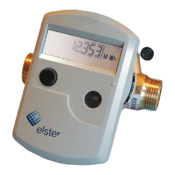
Compact Heat Meter
F90M AMS
Installation and Operating Instructions
1. Application and Function
This multi-jet compact heat meter F90M AMS type is
designed for measurement of the consumed heat energy in a
closed heating system.
2.
Contents of the Package
1.
Heat meter, consisting of a calculator, fl ow sensor and
two temperature sensors, all permanently connected to
each other.
2.
Installation kit: 2 self-lock seals, 2 sealing wires
1 black seal for the EAT (see illustration in section 4.1)
Installation kit wall support (only F90M AMS separable
3.
version)
4.
Installation and Operating Instructions
3.
General Information
• The valid standard for the application of heat meters is EN 1434,
parts 1 + 6. The regulations for electrical installations are to be
observed.
• The product meets the requirements relating to emissions in the
European Council Directive on EMC 2004/108/EC.
• The instrument identifi cation and the seals must not be dama-
ged or removed – otherwise the guarantee and the approved
application of the instrument no longer apply!
• The heat meter left the factory in conformance with all
applicable safety regulations. All maintenance and repair work
is to be carried out only by qualifi ed and authorized technical
personnel.
• The instrument must be stored and transported at above-
freezing temperatures. The storage and/or ambient temperature
must not fall below +5°C.
• All details and specifi cations listed on the data sheet of the heat
meter must be adhered to.
• Instruments with a return-fl ow temperature sensor mounted
directly in the fl ow sensor may only be mounted in the return
fl ow.
• All electrical connections must be laid at a minimum distance
of 50 cm to sources of electromagnetic interference (switches,
controllers, pumps, etc.). All instrument connections must be
laid at a minimum distance of 10 cm to other current-carrying
wires.
Elster Messtechnik GmbH, Otto-Hahn-Straße 25, 68623 Lampertheim
Tel: +49 (0) 6206 933 0, Fax: +49 (0) 6206 933 100, www.elstermesstechnik.com
Artikel-Nr. 0080100072 - 2010-08-23 (F90MAMS_M_09.03e / 08.10)
• The temperature sensor cables must not be kinked, rolled up,
lengthened or shortened.
• To clean the heat meter (only if necessary) use a slightly moist
(not dripping wet!) cloth.
• To protect against damage and dirt the heat meter should only be
removed from the packaging directly before installation.
• If more than one heat meter is installed in one unit, care must
be taken to ensure that all the meters have the same installation
conditions.
• Pay attention to the installation point of the heat meter:
standard: in the return fl ow pipe
optional: in the forward fl ow pipe (state when ordering).
• For meters with two declarations on the identifi cation plate, such
as: Q ≥ 100l/h ΔT: 3-100 K / Q ≥ 20l/h ΔT: 6-100 K the decla-
ration that is not valid for the local installation situation must be
made unrecognizable;
for example, for fl oor heating:
Q ≥ 100l/h ΔT: 3-100 K / Q ≥ 20l/h ΔT: 6-100 K
for example, for radiator heating:
Q ≥ 100l/h ∆T: 3-100 K / Q ≥ 20l/h ∆T: 6-100 K
• The measurement stability of the heat meters is only guaranteed
when the quality of the water meets the conditions as specifi ed
in the AGFW Recommendation FW-510. In the case that the
composition or consistency of the water deviates from these re-
quirements, the heat meters must be inspected and refurbished
regularly by the manufacturer.
• The direct-mounted temperature sensor or the plug on the tem-
perature sensor installation point may not be altered in any way,
in particular the sealing wire must not be removed.
4. Mounting the fl ow sensor
Note:
In order to simplify mounting in narrow
installation spaces the calculator can be
detached from the fl ow sensor.
Only for the separable version.
To detach the calculator, press
on the lateral surfaces shown in the
illustration and carefully lift off the top
part of the housing.
Page 1
Advertisement
Table of Contents

Related Manuals for Elster F90M AMS


Summary of Contents for Elster F90M AMS
- Page 1 AGFW Recommendation FW-510. In the case that the composition or consistency of the water deviates from these re- 1. Application and Function This multi-jet compact heat meter F90M AMS type is quirements, the heat meters must be inspected and refurbished regularly by the manufacturer.
- Page 2 EAT Elster Messtechnik GmbH, Otto-Hahn-Straße 25, 68623 Lampertheim Tel: +49 (0) 6206 933 0, Fax: +49 (0) 6206 933 100, www.elstermesstechnik.com Artikel-Nr. 0080100072 - 2010-08-23 (F90MAMS_M_09.03e / 08.10)
- Page 3 Up to the end of the month the consuption and reading date for that month will be shown as 0. Elster Messtechnik GmbH, Otto-Hahn-Straße 25, 68623 Lampertheim Tel: +49 (0) 6206 933 0, Fax: +49 (0) 6206 933 100, www.elstermesstechnik.com Artikel-Nr.
- Page 4 10.1. Optical (infrared) interface There are seven possible causes of error, and they can appear in In order for a PC to be able to communicate with a F90M AMS - combination with each other, depending on the situation. instrument, it is necessary to connect an optocoupler to the The discription of the faults can you see over the display.
- Page 5 The display must remain accessible and able to be read out one hand while pulling up the calculator housing with the other without auxiliary tools. hand. The wall mounting kit included in delivery for F90M AMS separable version: 2 screws 2 dowels...
Need help?
Do you have a question about the F90M AMS and is the answer not in the manual?
Questions and answers