Table of Contents
Advertisement
Quick Links
F96Plus
Ultrasonic Compact Energy Meter
Installation and User Guide
for software version F02-002
Brummerhoop & Grunow GmbH
Kurt-Schumacher-Allee 2 · 28329 Bremen · Phone +49 421 43560 0 · Fax +49 421 43560 18
info@brummerhoop.com · www.brummerhoop.com · Subject to technical adjustments · Version 2.1 ·25.06.2013
Advertisement
Table of Contents

Related Manuals for Elster F96Plus


Summary of Contents for Elster F96Plus
- Page 1 F96Plus Ultrasonic Compact Energy Meter Installation and User Guide for software version F02-002 Brummerhoop & Grunow GmbH Kurt-Schumacher-Allee 2 · 28329 Bremen · Phone +49 421 43560 0 · Fax +49 421 43560 18 info@brummerhoop.com · www.brummerhoop.com · Subject to technical adjustments · Version 2.1 ·25.06.2013...
-
Page 2: Table Of Contents
Contents General ....................4 About this Installation and User Guide ........4 1.1.1 Target groups ................4 1.1.2 Subject to change, validity ............4 1.1.3 Completeness ................4 1.1.4 Storage location ................. - Page 3 Unpacking the energy meter ............ 24 Transporting the energy meter ..........24 Storage of energy meter ............24 Installation ..................25 Installing the energy meter ............26 6.1.1 Installing the flow sensor............
-
Page 4: General
General About this Installation and User Guide This Installation and User Guide refers exclusively to the F96Plus ultrasonic energy meter and is part of the product. It describes how to use this product safely for the intended purpose throughout the product life cycle. -
Page 5: Symbols
1.1.6 Symbols The symbols used in this Installation and User Guide are explained below. Symbol Meaning This symbol is the safety sign. All measures marked with the safety sign must be observed. It is used on warning signs. This symbol is a safety sign indicating that the ESD (electrostatic discharge) regulations must be observed. -
Page 6: Safety
Safety NOTE Observe the following requirements before carrying out work of any kind. Intended use The ultrasonic energy meter is used for recording all billing data for local and district heating and cooling. 2.1.1 Misuse Operation of the meter outside the specified operating and environmental conditions is not permitted. Basic safety instructions 2.2.1 Product safety The ultrasonic energy meter is produced to the latest state of the art and the recognized safety... -
Page 7: Obligations Of Trained Personnel/User
installation and repair work work on the electronic circuits Safety equipment Safety equipment must be provided if required. E.g. install stop valves before and after the meter to simplify removal and installation. Warranty Obtain the manufacturer’s approval before carrying out modifications, repair work or changes during the warranty period. -
Page 8: Product Description
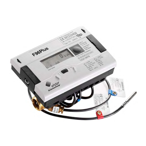
Product description Mechanical design Fig. A Design of ultrasonic energy meter LC display Pushbutton Optical ZVEI interface Flow sensor Laser labelling Scope of delivery The scope of delivery for the standard version includes the following: Ultrasonic energy meter Wall mounting set incl. fixing material ... -
Page 9: Functional Description
Labelling Fig. B Labelling (example) The meter is labelled using a laser. Conformity mark Year of declaration of conformity EC type examination certificate number Year of manufacture Meter serial number Meter article number Flow sensor data Calculator data Product name Functional description The ultrasonic energy meter is a static compact meter and a fully electronic measuring instrument based on the ultrasonic metering principle. -
Page 10: Power Supply
Power supply Possible power supplies: A cell, 3.6 V DC lithium battery, with a lifetime of 11 years (standard version, with radio) D cell, 3.6 V DC lithium battery, with a lifetime of 16 years Mains unit 24 V AC ... -
Page 11: Battery
3.5.1 Battery A 3.6 V DC lithium battery is fitted in the standard version. The battery is not to be charged or short- circuited. Ambient temperatures below 40 °C extend the life of the battery. DANGER There is a risk of explosion if the battery is replaced with the wrong type of battery. -
Page 12: Mains Unit
3.5.3 Mains unit The mains unit indicates to the meter if mains voltage is present. If the mains unit fails, the back-up battery (CR2032) in the mains unit provides the power supply for up to 1 year. This back-up battery can be replaced if necessary. -
Page 13: Communication Modules
The energy meter has two slots for extension modules, slot 1 and slot 2 (Fig. E). In addition, the meter can be equipped with an integrated radio. Fig. E Slots Slot 1 Slot 2 Fixing clip NOTE Inserting a module into slot 2 immediately disables the internal radio function! The meter recognizes automatically which module is inserted. -
Page 14: Function Modules
Communication via radio The integrated radio function is an interface for communication of predefined protocols with Hydrometer radio receivers. The communication protocol is preset, but can be defined to a customer- specific protocol using the IZAR@SET software. By default, the internal radio is disabled. When the meter detects a flow, the integrated radio is enabled. -
Page 15: Technical Data
Technical data Dimensions / weight Fig. F Dimensions of threaded version... - Page 16 Fig. G Dimensions of flange version : Values for PN16 housing : Meter with A-cell, without modules, 1.5m cable length, 2m cable length of temperature sensor Ø 5.2mm...
-
Page 17: General Data
General data Nominal size q : 0.6 – 60 m Ambient temperature: 5 … 55 °C Medium temperature: 5 … 130 °C (150 °C), depending on variant and nominal size Power supply External power supply 230 V AC module / 24 V AC module (Fig. C, item 2, page 10) ... - Page 18 Communication via integrated radio The integrated radio communication has the following specification: Unidirectional transmission The module sends every 8 ... 256 s (variable, depending on protocol length) typical radio transmitting power 10 dBm ≙ 10 mW Data actuality: online – no time delay between recording readings and data transfer ...
-
Page 19: Function Modules
L-Bus 2 wire terminal with marking “Dat“ and “┴“ Terminals suitable for a cable with 2 wires of 2.5 mm² Maximum voltage: 50 V DC Primary or secondary addressing Baud rate 300 or 2400 baud (automatic baud rate detection) ... - Page 20 Pulse output module External power supply necessary Vcc = 3 – 30 V DC Output current ≤ 20 mA with a residual voltage of ≤ 0.5 V Open collector (drain) The module consists of 2 programmable pulse outputs ...
- Page 21 Module IN-OUT (Pulse-in and -output) The module IN-OUT is equipped with 2 pulse inputs and 1 pulse output. The pulse inputs have the following specification: The two pulse inputs can be programmed independently of each other with values of 1, 2.5, 10, 25, 100, 250, 1000 or 2500 litres per pulse.
- Page 22 Analogue output module 2 passive outputs External power supply: 10 … 30 V DC Current loop 4 … 20 mA where 4 mA = 0 value; 20 mA = programmed max. value Overload up to 20.5 mA, then fault current ...
-
Page 23: Test Output
4.4.3 Test output The test output located on the side of the main electronics assembly is for use by test centres (Fig. Q). Fig. Q Test output Connection for test cable Two special cables are required for testing: 1. Test cable for volume test pulses (Order. Nr 3029794) 2. -
Page 24: Transport, Storage
Transport, storage Unpacking the energy meter Heat meters and cooling meters are measuring instruments and must be handled carefully. To protect against damage and soiling, they should not be removed from the packaging until shortly before installation. Transporting the energy meter The meter is only to be transported in its original packaging. -
Page 25: Installation
Installation NOTE This installation guide is intended for trained personnel and does not contain any basic working steps. The meter may only be installed in dry and frost-free areas in buildings. Avoid sharp edges (thread, flange, measuring tube). Only install and remove the meter when the system is not under pressure. -
Page 26: Installing The Energy Meter
Fig. R Seals Seal Cable bushings Installing the energy meter CAUTION If medium temperature is lower than ambient temperature! Risk of damage to calculator due to condensation. Use the sealed variant of the ultrasonic energy meter. Remove calculator from the flow sensor (Fig. V, page 29) and install remotely. NOTE Install the meter in an accessible position for service and operating personnel. -
Page 27: Installing The Flow Sensor
The following tasks are necessary for installing the energy meter: 1. Install the flow sensor, see Section 6.1.1 2. Install the calculator, see Section 6.1.2 3. Connect the temperature sensor, see Section 6.1.3 4. Install the temperature sensor, see Section 6.1.4 6.1.1 Installing the flow sensor NOTE Thoroughly flush out the system before installing the flow sensor. -
Page 28: Installing The Calculator
1. Install the flow sensor so that the direction of the arrow on the sensor corresponds to the direction of flow (Fig. T). Fig. T Direction of flow Arrow indicating direction Direction of flow 2. Ensure that the flow sensor is always filled with water. The meter only measures the energy if the pipes are completely filled, otherwise a corresponding error message is shown in the display. - Page 29 Fig. V Remote calculator Fig. W Wall mounting Wall mounting adapter (supplied with meter) Fig. X Spacer holder (not supplied with meter)
-
Page 30: Connecting Temperature Sensor
6.1.3 Connecting temperature sensor NOTE The meter is operated with separately approved pair of Pt 100 or Pt 500 temperature sensors. The type of sensor to be used is printed at the front of the calculator. Ensure that the approved temperature range of the temperature sensors is the same as the temperature range of the calculator! A temperature sensor is normally installed in the flow sensor for nominal sizes from q 0.6 m³/h to 2.5 m³/h. - Page 31 2. Connect the sensor cables to terminals 5-6 / 7-8 (Fig. Z, page 31) as shown in the following table. Sensor Meter type Terminal Installation position marking Energy meter in In the hot pipe cold pipe Blue In the meter Cold Energy meter in hot In the meter...
-
Page 32: Installation Of The Temperature Sensors
6.1.4 Installation of the temperature sensors NOTE The temperature sensors are to be installed symmetrically in the forward and return line and preferably direct. The free temperature sensor can be installed in a ball valve or in a pocket conforming to the requirements for this type of sensor. The forward and return sensors must be inserted as far as the bottom of the pocket and then fixed in position. - Page 33 4. Insert the O-ring with the mounting pin in the sensor hole of the ball valve using turning movements (Fig. AA, item 3). 5. Position the O-ring in its final position using the other end of the mounting pin (Fig. AA, item 4). 6.
-
Page 34: Installing Extension Modules
Installing extension modules The energy meter has two slots for extension modules. CAUTION Do not insert modules in the wrong slots. Risk of damage to calculator! Install modules in the correct slots. NOTE These modules have no effect on consumption recording and can be fitted retrospectively without damaging the verification mark. - Page 35 Overview of the possible combinations for the modules for slot 1 and 2 interface / slot 2 • no module • • • • • M-Bus • RS232 • RS485 • • • • • pulse input • • • • • •...
- Page 36 1. Remove the seal from the calculator housing and open the calculator by releasing the side catches. Take the top part of the calculator and turn it so that the inside of the calculator is facing you. You can simplify installing the modules by using the two openings in the top part to place this on the bottom part (Fig.
-
Page 37: Display Of The Slot Configuration
6.2.1 Display of the slot configuration The F96Plus is equipped with an automatic detection which module is mounted in which slot (port). This detection will be shown in the display in loop 3 in two different sequences for port 1 resp. -
Page 38: Connecting Modules
Module type Module code in the display Combined Pulse in-/ output Test cable energy Test cable volume L-Bus (for external radio) Connecting modules 6.3.1 Connecting communication modules M-Bus module NOTE The board contains a 2 wire terminal with marking 24, 25 (Fig. H, page 17). ... -
Page 39: Connecting Function Modules
L-Bus module NOTE The board contains a 2 wire terminal with marking “Dat“ and “┴“ (Fig. K, page 19). Connect the cable of the external radio module with the marked terminals. 6.3.2 Connecting function modules Pulse input module NOTE The board contains a 4 wire terminal with marking “I1 - ”... -
Page 40: Connecting The Mains Voltage 230 V / 24 V
Analogue output module NOTE The board contains two 2 wire terminals for the two analogue outputs; output 1 is marked “+ 1 –” and output 2 “+ 2 –” (Fig. P, page 22). Connect the cable for analogue output 1 to the terminals marked “+” and “-” of terminal 1. Connect the cable for the second analogue output to the terminals marked “+”... -
Page 41: Programming The Energy Meter
Programming the energy meter NOTE A number of settings can be programmed in the meter using the IZAR@SET software. More information is available at www.hydrometer.de. -
Page 42: Taking Into Operation
Taking into operation The meter can be taken into operation once it has been installed. Proceed as follows: Open the stop valves. Check the system for leaks. Carefully bleed the system. The message “E – 7” disappears from the display after a short time. ... -
Page 43: Operation
Operation Display The meter readings are displayed with units and symbols on an 8-digit LCD. Quadrant display Loop display Flow rate indicator Tariff energy Maximum values Marking for the calibrated value, which is Error symbol allowed to be used for billing Operation of meter A pushbutton mounted on the front of the meter is used to switch to the various displays. - Page 44 The basic display shows the “Energy” window in the main loop when the meter is attached to the pipe, the pipe is completely filled with water and there is no error (sequence 1.1). If there is an error it is shown permanently in the basic display.
-
Page 45: Display Indications (Default Settings)
Display indications (default settings) Main loop (1) Sequence Window 1 Accumulated energy ▼ Volume ▼ (Sequence only in a heat meter with cooling tariff) Accumulated energy (cooling) ▼ Flow rate ▼ Power ▼... - Page 46 Sequence Window 1 Forward/- Return temperature ▼ Temperature difference ▼ Operating days error hours ▼ Error code ▼ 1.10 Display test ▼ Sequence 1.1...
- Page 47 Accounting date loop (2) Sequence Window 1 Window 2 Window 3 Accounting date 1 Accounting date 1 energy ‚Accd 1A’ ▼ ‚Accd 1’ Future accounting date 1 ▼ Accounting date 1 Accounting date 1 ,Accd 1L’ previous year previous year energy ▼...
- Page 48 Sequence Window 1 Window 2 Window 3 Accounting date 1 Pulse input 1 Pulse input volume 1 ▼ Accounting date 1 Pulse input 1 Pulse input volume 1 previous year ▼ Accounting date 2 Pulse input 1 Pulse input volume 1 ▼...
- Page 49 Sequence Window 1 Window 2 Window 3 2.13 Accounting date 2 Pulse input 2 Pulse input volume 2 ▼ 2.14 Accounting date 2 Pulse input 2 Pulse input volume 2 previous year ▼ Sequence 2.1 Info loop (3) Sequence Window 1 Window 2 Current date Current time...
- Page 50 Sequence Window 1 Window 2 Installation position ▼ ‚Port 1’ No. of mounted module in Port 1 ▼ ‚Port 2’ No. of mounted module in Port 2 ▼ (Sequence only in a meter with integrated radio) Status of integrated radio ▼...
- Page 51 Impulse loop (4) Sequence Window 1 Window 2 Window 3 Pulse input 1 Accumulated value Pulse value 1 [L/P] ▼ pulse input 1 (pulse per increment, depends on the decimal place of the accumulated value, here 1L/pulse) Pulse input 2 Accumulated value Pulse value 2 [L/P] ▼...
- Page 52 Tariff loop (5) (Only in a heat meter with cooling tariff) Sequence Window 1 Window 2 Window 3 Tariff counter 1 Tariff type 1 Tariff limit 1 ▼ (° appears when tariff condition is fulfilled) Accounting date 1 Accounting date 1 ,Accd 1A’...
- Page 53 Sequence Window 1 Window 2 Window 3 Tariff counter 3 Tariff type 3 Tariff limit 3 ▼ (° appears when tariff condition is fulfilled) Tariff counter 4 Tariff type 4 Tariff limit 4 ▼ (° appears when tariff condition is fulfilled) Sequence 5.1 Monthly value loop (6) (Heat - or cooling meter) Sequence Window 1...
- Page 54 Monthly value loop (6) (heat meter with cooling tariff) Sequence Window 1 Window 2 Window 3 Window 4 Window 5 Window 6 ‚LOG’ Date of last month Energy Tariff counter Tariff counter Volume ▼ ‚LOG’ Date of month – 1 Energy Tariff counter Tariff counter...
-
Page 55: Maintenance And Repair
Maintenance and repair NOTE Information concerning repair and maintenance can be obtained from the Repair Concept. -
Page 56: Testing
Testing NOTE Information concerning testing can be obtained from the relevant Inspection and Test Instruction. Test information can also be found in the EC type examination certificate of the meter under 5.1 (Test documentation) and in EN 1434-5. The number of the type examination certificate is printed on the calculator of the meter. -
Page 57: Removal
Removal CAUTION Danger due to escape of heat medium. Risk of burns! Close the stop valves before removing the meter. Remove the energy meter. 11.1 Disposal of energy meter NOTE The meter contains a lithium battery. This must not be opened by force, come into contact with water, be short-circuited or exposed to temperatures above 85 °C. -
Page 58: Error Analysis
Error analysis The meter continuously monitors its own operation and displays various error messages. The error code is displayed in the main loop if an error occurs. The permanent display shown corresponds to the “normal” display (e.g. a temperature sensor error is not shown in the flow rate display). In the basic display mode, the display changes between error codes 1, 4 and 7 and the basic display (exception: error display “C - 1”... -
Page 59: Declaration Of Conformity
Declaration of conformity...
Need help?
Do you have a question about the F96Plus and is the answer not in the manual?
Questions and answers