Table of Contents

Related Manuals for Elster A1100


Summary of Contents for Elster A1100
- Page 1 A1100 Electronic Polyphase Meter Operating & Maintenance Instructions M180 001 1E 7.2005 The company’s policy is one of continuous product improvement and the right is reserved to modify the specification contained herein without notice...
-
Page 3: Table Of Contents
TEPPER EGISTER COMMUNICATIONS.......................... 18 13.1 DA C ........................18 OMMUNICATIONS 13.2 ........................ 18 PTIONAL ERIAL 13.3 ..........................19 RANSMITTED PULSING OUTPUT..........................20 AUXILIARY VOLTAGE TERMINALS ....................21 TECHNICAL DATA..........................22 © Elster Metering Systems - M180 001 1E - 6.2005... - Page 4 APPENDIX C - IRDA DATA SOFTWARE ...................... 47 ............................. 47 NTRODUCTION C1.1 Installing the Software ........................47 C1.2 Collecting Data Using a Laptop ......................47 C1.3 Collecting Data Using a PDA ......................49 © Elster Metering Systems - M180 001 1E - 6.2005...
-
Page 5: Foreword
The purchaser is responsible for making sure that everyone, whether in his employment or not, who will be associated with the products supplied by Elster Metering Systems, and to which these instructions and information apply, are made familiar with the contents of this manual. -
Page 6: Warnings
The CE Mark does not denote compliance with the European Low Voltage Directive 73/23/EEC, which specifically excludes electricity meters. The A1100 meter measures active energy, according to the requirements of EN 61036 1996 (plus amendment 1:2000) for indoor kWh meters of protective Class II and accuracy Class 1 or Class 2. -
Page 7: Introduction
The A1100 is an electronic polyphase meter for domestic, commercial and light industrial CT or direct connected applications. Two main versions of the A1100 meter are available. The liquid crystal display version of the meter can be supplied with one or two rates. The meter is available as import only or import and export. -
Page 8: General Description
Meter nameplates (see Figure 3 for example) are marked with the rated current, reference voltage, frequency and relevant meter constant (pulses/kWh). Connection diagrams (See Figure 5A for examples) are shown underneath the terminal cover. © Elster Metering Systems - M180 001 1E - 6.2005... -
Page 9: Meter Configurations
Single rate, kWh import plus reverse (power flow insensitive) Meter Accuracy The A1100 meter measures active energy, in accordance with the requirements of EN 61036:1996 (plus amendment 1:2000) for indoor kWh meters of protective Class II and accuracy Class 1 or Class 2. -
Page 10: Time Of Use Registers
Import/export meter - The LED pulses for forward and export energy For loads above import and export starting current, this gives 40ms pulses modulated at approximately 8kHz to provide improved detection by electronic meter test equipment. © Elster Metering Systems - M180 001 1E - 6.2005... -
Page 11: Security Features
Operating & Maintenance Instructions Anti-creep The Wh anti-creep threshold is set at manufacture to a value suitable for the number of elements in the meter. The Test Indicator LED is continuously illuminated when the meter's anti-creep lock is operating. SECURITY FEATURES Table 1 below shows security features for each meter type: Table 1 Security Features... -
Page 12: Recordable Security Features
Each complete hour the meter is active in Rate 1 and Rate 2 is recorded in separate registers. 11.4 Meter Errors The A1100 detects and reports the following errors according to the meter type: Error Type LCD Meter Stepper Register Meter... -
Page 13: Meter Register And Displays
Operating & Maintenance Instructions METER REGISTER AND DISPLAYS The A1100 meter can be fitted with a mechanical stepper type register or a liquid crystal display. Two rate meters and import/export meters are available only with the LCD meter. 12.1 Liquid Crystal Display The LCD is a high contrast display that can be viewed from a wide angle. -
Page 14: Display Modes
L1 - Phase A present/failed L2 - Phase B present/failed L3 - Phase C present/failed Security data Active rate – Rate displayed is currently active TOU 1 currently displayed TOU 2 currently displayed © Elster Metering Systems - M180 001 1E - 6.2005... - Page 15 Operating & Maintenance Instructions The following data items may be included in the display sequence, in the order shown. Segment Test Pattern TOU 1 The test display is always displayed at power up. TOU 2 All segments should be 'on'. kWh import L1 L2 L3 Active...
-
Page 16: Rate Meter
TOU 1 TOU 1 export kWh register reading TOU 2 TOU 2 export kWh register reading TOU 1 and TOU 2 Cumulative export kWh (TOU 1 plus TOU 2) register reading © Elster Metering Systems - M180 001 1E - 6.2005... - Page 17 Operating & Maintenance Instructions Phase Present/Phase Failure Three Chevrons are used to indicate if a phase is present or failed. Chevron 3 (phase A), chevron 4 (phase B) and chevron 5 (phase C) can be programmed at manufacture to be 'on' (default condition) if a phase is present or to be 'off' when a phase is present.
- Page 18 Each time a phase failure is detected a counter is incremented. This count (maximum 65535) can be included in the display sequence. Displayed Chevron Reference Indicator Action 6 - Security Phase Failure Counter © Elster Metering Systems - M180 001 1E - 6.2005...
-
Page 19: Display Multiplier (Ct Operated Meters)
Operating & Maintenance Instructions 12.4 Display Multiplier (CT operated meters) The CT operated meter does not allow a CT ratio to be entered into the meter, only a transformer secondary value. To calculate the actual meter reading the displayed value must be multiplied by the transformer ratio. -
Page 20: Communications
If this option is used the baud rate is the same for both ports and can be set to either 2400 or 4800 baud. The port will transmit over a distance of up to 3m. © Elster Metering Systems - M180 001 1E - 6.2005... -
Page 21: Transmitted Data
Operating & Maintenance Instructions 13.3 Transmitted Data The following data is available via the IrDA and Serial Data port (optional): 1. Absolute meter readings 2. Security register, status and identification data The following data is transmitted via the IrDA port and serial data port. •... -
Page 22: Pulsing Output
(1), (2) see below re: representation of consumption. Note: Care should be taken in selecting the combination of pulse width and pulses /kWh. Avoid combinations that may give insufficient spacing between pulses at maximum load. © Elster Metering Systems - M180 001 1E - 6.2005... -
Page 23: Auxiliary Voltage Terminals
The Pulse output meets the requirements of IEC 62053-31. See Figure 5 (Terminal Arrangements) for connections. AUXILIARY VOLTAGE TERMINALS As an option the A1100 can be supplied with additional terminals that allow external equipment to be powered from the meter (See Figure 5). -
Page 24: Technical Data
Note 1 The contrast of the LCD may be impaired at temperatures lower than -20° C. This will not however damage the display and the contrast will return to normal when the temperature rises above -20° C. © Elster Metering Systems - M180 001 1E - 6.2005... -
Page 25: Installation
Check that there is no movement or loose parts within the meter enclosure. If damage has been sustained in transit, an immediate claim should be made to the Transport Company, and a report sent to the Elster Metering Systems branch office or agent. WARNING Removal of meter seals will invalidate certification. -
Page 26: Fixing And Connection
Tighten screws just sufficiently to prevent movement of the meter. WARNING Do not over-tighten the screws or the meter base may be damaged. © Elster Metering Systems - M180 001 1E - 6.2005... -
Page 27: Commissioning
Operating & Maintenance Instructions For connecting to the large diameter terminals, strip back the cable insulation by 26mm. Fully insert cables into the terminals so that the insulation butts up into the counter-bored recesses in the bottom face of the terminal block. Using a Number 2 Phillips or flat blade screwdriver, tighten the M6 terminal screws to a torque of between 2.2N m minimum, 3.0N m maximum. -
Page 28: Disposal And Recycling
Major plastic parts are marked with recycling information. On the disposal of a meter, every endeavour should be made to comply with local environmental legislation regarding recovering materials and waste disposal. © Elster Metering Systems - M180 001 1E - 6.2005... -
Page 29: Figures Figure 1 - Model Code
Operating & Maintenance Instructions MODEL TYPE (nameplate) Example: L B 3 A A B B B S N N S - A N PRODUCT/TERMINATION Poly- Phase, BS/DIN termination SERVICE TYPE 3Ph 4W (Plus 1 ph 2w for LCD version) 3ph 3w CURRENT RANGE Direct Connected 20A –... -
Page 30: Igure Mcodel Code Continued )
Note 3:- PULSE OUTPUT VALUES The following values are for the Test Indicator LED output Direct Connected: 500 p/kWh CT Operated: 5000 p/kWh (CT ratio cannot be entered Figure 1A - Model Code (continued) © Elster Metering Systems - M180 001 1E - 6.2005... -
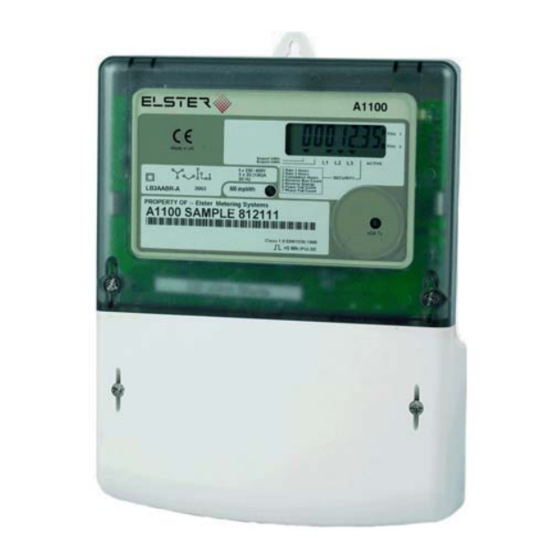
Page 31: Figure 2 - Liquid Crystal Display Meter
Operating & Maintenance Instructions Nameplate (see Figure 3) Display (see Section 12.1) Chevron Indicators (see Section 12.1) Pulse LED (see Section 10) IrDA Port LED (see Section 13.1) Figure 2 – Liquid Crystal Display Meter... -
Page 32: Igure Stepper Register Meter Lcd Nameplate
Reverse Run LED (see Section 11.3.1) Phase Present/Phase Failed LED's L1, L2 and L3 (see Section 11.2) Pulse LED (see Section 10) IrDA Port LED (see Section 13.1) Figure 2A – Stepper Register Meter © Elster Metering Systems - M180 001 1E - 6.2005... -
Page 33: Figure 3 - Nameplates
Operating & Maintenance Instructions LCD Nameplate A1100 TOU 1 TOU 2 Made in UK Import kWh ACTIVE Export kWh EN 61036:1996 LB3AABTS-A SECURITY 3 x 230 / 400V Class 1.0 50 Hz 500 imp/kWh Wh/PULSE 3 x 20 (100)A Stepper Register Nameplate... -
Page 34: Figure 4 - Load Curves (Class 1 Limits)
Load Curve 5 – 85A Meter 5(85)A [0-100A] -0.5 -1.5 Load (A) Legend: Class 1 +ve/-ve UPF Limit UPF Error 0.5PF Lag Error Figure 4 - Load Curves (Class 1 Limits) © Elster Metering Systems - M180 001 1E - 6.2005... -
Page 35: Figure 5 - Terminal Arrangements
Operating & Maintenance Instructions Auxiliary Configurations 3phase 4 wire meters Note: Connections available for 3 phase 3 wire meters are shown in brackets 27V DC 230V 20 21 2A (max) 2A (max) A, B or C A, B or C (A or C) Neutral Neutral... -
Page 36: Igure Terminal Configurations
Note: 1ph 2w connection is not available for stepper register meters Note: These diagrams are examples only. WARNING Meters must be wired as shown on the diagram fitted under the meter terminal cover. Figure 5A – Terminal Configurations © Elster Metering Systems - M180 001 1E - 6.2005... -
Page 37: Figure 6 - Dimensions, Fixing Centres And Terminal Cover With Cut-Out
Operating & Maintenance Instructions Side View Back View 49mm 171.5mm 139mm 121mm 220mm 150mm Figure 6 – Dimensions, Fixing Centres and Terminal Cover with Cut-out... -
Page 38: Figure 7 - Typical Single Rate Import Meter Display
3 x 230 / 400V Class 1.0 50 Hz 500 imp/kWh 5. L3 - Phase C present/failed Wh/PULSE 3 x 20 (100)A 6. Security data Figure 7 - Typical Single Rate Import Meter Display © Elster Metering Systems - M180 001 1E - 6.2005... -
Page 39: Igure Typical Two Rate Import Meter Display
Power Fail Count Phase Fail Count Rate 1 Plus Rate 2 Phase A Not present Chevron Position on Display with Typical Nameplate 1. kWh A1100 2. Reverse alarm 3. L1 - Phase A present/failed TOU 1 TOU 2 Made in UK Import kWh 4. -
Page 40: Display Data (Lcd Meter )
For 1 or 2 hours after power up Error Reporting Error (Optional) Hardware Error Er00001 Configuration Checksum Error Er00010 Billing Data Checksum Error Er00100 Figure 7B – Display Data (LCD Meter) © Elster Metering Systems - M180 001 1E - 6.2005... -
Page 41: Appendix A - Irda Data Formats
APPENDIX A – IRDA DATA FORMATS Introduction The A1100 uses the OBIS (OBject Identification System to IEC 62056-61) data identifiers to transmit data via its IrDA Port and serial data port. The port continuously transmits the meters registration, security and status data. -
Page 42: A3 Irda Data Bits
Note that the bits are actually transmitted least significant bit first – thereby the first data bit is always a logic’1’. Transmission Translation Table :- Data Nibble (4 bit hex) Transmitted Data (8 bit hex) © Elster Metering Systems - M180 001 1E - 6.2005... -
Page 43: A4 Irda Message Format
The table is made up of non-contiguous memory. It includes data stored in RAM, ROM, and EEPROM. OBIS Code Description FIELD NAME Product Code Product code. Eg: "A1100" 96.1.1 Firmware Rev Code Firmware revision code. Eg: "2-01162-A" 0.2.0 Mfg Serial Number Manufacturing serial number 96.1.0... - Page 44 Bit 4: Phase A Failed. 1 = failure Bit 3: Phase B Failed. 1 = failure Bit 2: Phase C Failed. 1 = failure Bit 1: not applicable Bit 0: not applicable © Elster Metering Systems - M180 001 1E - 6.2005...
- Page 45 Operating & Maintenance Instructions OBIS Code Description FIELD NAME Error Flags 97.97.0 Error flags: Bit 7-6: Reserved Bit 5 ROM checksum error; 1 = error Bit 4 Table 1 checksum error; 1 = error Bit 3: Table 0 checksum error; 1 = error Bit 2: Billing data checksum error;...
-
Page 46: Appendix B - Checking Kwh Registration Accuracy
A counter for counting the number of LED pulses Checking registration In order to achieve a repeatability of 0.1% in the accuracy of the A1100 test indicator, the test time at any load needs to be a minimum of 35 seconds. -
Page 47: B2.2 Comparing Led Pulses With Substandard Meter Pulses
Operating & Maintenance Instructions B2.2 Comparing LED pulses with substandard meter pulses This method may be used where the test equipment has the facility to calculate meter errors based on the pulse output from a substandard meter. It will be necessary to set the pulse value of the meter under test (shown on the meter nameplate) into the meter test equipment. -
Page 48: B3.2 Using The Register Readings From The Irda Output
Laptop, PC or PDA IrDA Software - Various software packages are available. The software package described in Appendix C is available from Elster Metering Systems. It is suggested that this software is installed in a folder called A1100 IrDA Reader. -
Page 49: Appendix C - Irda Data Software
PDA (Personnel Digital Assistant). For collecting from a PC it is suggested the software is installed in a folder called A1100 IrDA Reader. An IrDA data receiver will be required. This should be connected to a suitable port on the PC. - Page 50 Phase fail count Power fail count Watchdog count Reverse run count Text Output The text output allows the following meter data to be viewed: Meter identification Meter data Status information © Elster Metering Systems - M180 001 1E - 6.2005...
-
Page 51: C1.3 Collecting Data Using A Pda
C1.3 Collecting Data Using a PDA The PDA must be loaded with relevant A1100, IrDA meter reading software. To read the data the PDA should be held pointing reasonably square to the IrDA port at a distance of approximately 10cm to 30 cm.
Need help?
Do you have a question about the A1100 and is the answer not in the manual?
Questions and answers