
Related Manuals for Elster EK220


Summary of Contents for Elster EK220
- Page 1 EK220 Volume Conversion Device EK220 Operating Instructions and Installation Information Operating Manual: 73020052 SW Version: from V1.20 Issued 01.09.2008 (b) Edition:...
- Page 2 Volume Conversion Device EK220 © Elster GmbH...
- Page 3 Further support is available from your local branch office / agent. The addresses are avail - able on the internet or from Elster GmbH. Passing this manual to third parties and its duplication, in full or in part, are only allowed with written permission from Elster GmbH.
-
Page 4: Table Of Contents
Volume Conversion Device EK220 Contents Safety information........................6 Items supplied and accessories ....................7 Brief description........................8 Operation..........................10 Front panel ........................10 Display ..........................11 2.2.1... - Page 5 5.7.4 Other devices with RS232 interface, EK220 battery powered..........100 5.7.5 Other devices with RS232 interface, EK220 with external power supply........ 100 Seals ..........................101 5.8.1 Seal layout of basic device ....................102 5.8.2...
-
Page 6: I Safety Information
Make sure that the limits quoted in the EC prototype test certificate (see Appendix A-2) for the devices to be connected are not exceeded. The housing of the EK220 must be earthed directly to a potential equa lisation strip. A terminal screw is provided for this on the left housing wall. -
Page 7: Items Supplied And Accessories
Volume Conversion Device EK220 Items supplied and accessories Items supplied: The items supplied with the EK220 include: a) EK220 Volume Conversion Device b) Dispatch list c) Configuration data sheet d) Operating Manual e) Bag of accessories, EK220 Ordering information and accessories Order no. -
Page 8: Brief Description
Volume Conversion Device EK220 1 Brief description The EK220 Volume Conversion Device is used for the conversion of the gas volume measured in the operating state by a gas meter to the standard state and in the appropr i- ate energy. - Page 9 Volume Conversion Device EK220 Short message via SMS · Programmable standard output data records for process data ("three -minute values"). · Pressure sensor: Pressure sensor integrated in device, or external mounted. · Connection of second pressure sensor possible (option). ·...
-
Page 10: Operation
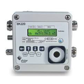
Volume Conversion Device EK220 2 Operation Front panel The following are positioned on the front panel for operation: · Two-line alphanumeric display with 16 characters per line. · Four keys for the display and entry of values. Identification label © Elster GmbH... -
Page 11: Display
Volume Conversion Device EK220 Display Basic display structure (with an example): Prefix Archive Device status M e n u Æ á A W B A c t. V. à Submenu V m A 1 2 3 4 5 6 7 8 9 Both lines in the display are subdivided into fields which are described below. - Page 12 Volume Conversion Device EK220 3. Device status Here a maximum of three of the most important items of status information are continually shown. A flashing character signifies that the corresponding state is still present and the corr e- sponding message is present in the momentary status.
-
Page 13: Line 2 = Value With Name And Unit
Volume Conversion Device EK220 2.2.2 Line 2 = Value with name and unit In the second line the name, value and (when available) the unit of the data are always shown. Example: V m A 1 2 3 4 5 6 7 8 9... -
Page 14: Changing Values
"data classes" (abbreviation: "DC"). Values in the same data class are treated identically during entry. A prerequisite for an entry is that the lock assigned to the value is open. The following data classes (DC) are present in the EK220: Type Entry, change using "ENTER"... -
Page 15: Entering "Sources
Volume Conversion Device EK220 2.3.2 Entering "sources" At a number of points the entry of a "source" is required for parameterisation (e.g. SC.Qb in the standard volume list, SC.A1 in the output list). The address of the desired value is entered as the source. It can be found in the tables at the beginning of each list (Chapter 3.1 ff.). -
Page 16: Access Rights
Volume Conversion Device EK220 Access rights The EK220 differentiates between four access parties. Each access party has a lock and a corresponding code. The locks have the order of priority Calibration lock – Manufacturer's lock – Supplier's lock – Customer lock. -
Page 17: Certification Data Log
St.PL, Cod.C) Formation of the list structure The data display in the EK220 is structured in a tabular form. The individual columns in the table each contain associated values. Values identified with S and Arc are submenus or archives which you can view by ente r- ing <ENTER>... - Page 18 Volume Conversion Device EK220 User list Standard volume Actual volume Pressure User Std.V. Act.V. Press „Energ.“ „Temp.“ « Vb « Vb « Vm « p « Vol. at base cond. Vol. at base cond. Actual volume Pressure (pre-dec. places) (post-dec. places) pMin Actual vol.
- Page 19 Volume Conversion Device EK220 Temperature Conversion Archive Status + Logbook Temp. Conv. Archiv Status „Press“ „System“ « C « T « ArMo1 Arc « S.Reg S « Temperature Conversion factor Month archive 1 Status register TMin ArMo2 Stat Compressibility Lower alarm limit...
- Page 20 Volume Conversion Device EK220 System Service Inputs System Serv. Inputs „Status“ „Outp.“ « Time « Bat.R « « cp.I1 Date and time Remaining bat. life cp-value Input 1 Bat.C cp.I2 MdTim Daylight sav.: y- Battery capacity cp-value Input 2 es/no St.SL...
- Page 21 Volume Conversion Device EK220 Outputs Interfaces Energy Outp. Ser.IO Energy „Inputs“ „User“ « Md.O1 « Md.S2 « W « Mode for output 1 Mode interface 2 Energy SC.O1 DF.S2 Source for output 1 Data format interface 2 Power cp.O1 Bd.S2...
-
Page 22: Functional Description
Volume Conversion Device EK220 3 Functional description The data display is structured in tabular form (list structure) ( ® 2.5). The individual col- umns in the table each contain associated values. The following functional description is orientated to this list structure. -
Page 23: User-Liste
Volume Conversion Device EK220 User-Liste Designation / value Unit Access Address DC Volume at base conditions (pre-decimal places) m3 C / S 2:300_1 12 Vm adjustable 4:303 Pressure 7:310_1 Temperature °C 6:310_1 Compressibility factor 9:310 Compressibility factor at base conditions... -
Page 24: Standard Volume (Volume At Base Conditions) List
Date and time of Vm month end value These values are also displayed in other lists and are described in the appropriate chapters. Menu Selection display menu With Menu the complete display structure of the EK220 can be switched between "complete" and "simple". Menu = Meaning Complete display structure Only "User"... - Page 25 Volume Conversion Device EK220 Vb disturbed Here the volume at base conditions is summed while ever an alarm is present, i.e. a message with the number "1" or "2" is located in any momentary status ( ® 3.8). In the alarm state the volume at base conditions is computed with the substitute values of the disturbed quantities.
-
Page 26: Actual Volume (Volume At Measurement Conditions) List
Actual flow rate Momentary actual flow (actual flow rate). If the EK220 receives fewer than four pulses per hour on the counter input (termi- nal "DE1"), the flow rate is set to "0". The maximum inaccuracy of the indicated value corresponds to four pulses. -
Page 27: Pressure List
The values displayed in this list depend on whether a second pressure sensor is co n- nected to the EK220 and is activated via Sel.p2 (see Chapter 3.10 ). a) One pressure sensor connected to the EK220, Sel.p2 = 0 ("off"):... - Page 28 Volume Conversion Device EK220 b) Two pressure sensors connected to the EK220, Sel.p2 = 1 ("CT30"): Designation / value Unit Access Address DC Pressure 7:310_1 pMin Lower alarm limit pressure 7:3A8_1 pMax Upper alarm limit pressure 7:3A0_1 MRL.p Pressure meas. range lower limit 6:224_1 MRU.p...
- Page 29 2. Apply measurement pressure 2 (= reference value 2) to the pressure sensor and enter as pAdj2. 3. Enter Prog = "1" so that the EK220 calculates the equation coefficients. After applying the measurement pressure, you should eith er wait about one minute...
-
Page 30: Submenu Pressure Sensor 2 „ Smenu Press. 2
Volume Conversion Device EK220 SMenu Press2 Here, <ENTER> is used to recall the submenu for the parameters of the second pressure sensor (® 3.4.1). p2Mes Pressure measurement p2Mes is the pressure measured by the second pressure sensor. Depending on the pressure sensor, p2Mes is displayed as the absolute pressure or overpre s- sure. - Page 31 To adjust the pressure measurement, the 3 coe fficients of the quadratic equation can either be found by the EK220 itself or calculated and entered by the user. External to the EK220, the three coefficients can be calculated based on three values for Binp2 and the corresponding reference values.
-
Page 32: Submenu Pressure Coefficients
To adjust the pressure measurement, the 3 coefficients of the quadratic equation can either be found by the EK220 itself or calculated and entered by the user. External to the EK220, the three coefficients can be calculated based on three values for Bin.p and the corresponding reference values. - Page 33 Volume Conversion Device EK220 b) Pressure sensor type 17002, Sel.p = 4 ("17002"): Designation / value Unit Access Address DC a0p1 Coefficient a0 of pressure equation C / S 6:290_1 a1p1 Coefficient a1 of pressure equation 6:290_2 a2p1 Coefficient a2 of pressure equation...
-
Page 34: Temperature List
Volume Conversion Device EK220 Temperature list Designation / value Unit Access Address DC Temperature °C 6:310_1 TMin Lower alarm limit temperature °C 6:3A8_1 TMax Upper alarm limit temperature °C 6:3A0_1 MRL.T Temperature meas. range lower limit °C 5:224_1 MRU.T Temperature meas. range upper limit °C... - Page 35 2. Apply measurement temperature 2 (= reference value 2) on the temperature sensor and enter as TAdj2. 3. Enter Prog = "1" so that the EK220 calculates the equation coefficients. After applying the measurement temperature, you should either wait about one...
-
Page 36: Submenu Temperature Coefficients
T.Mes = Eq1T + Eq2T ž Bin.T + Eq3T ž Bin.T To adjust the temperature measurement circuit, the three coefficients of the quad- ratic equation can either be found by the EK220 itself or calculated and entered by the user. - Page 37 Volume Conversion Device EK220 b) Computation according to AGA-NX19 (Md.K = 2) Designation / value Unit Access Address DC Conversion factor 5:310 K-value 8:310 Pressure at base conditions for gas analysis input bar 7:314_1 Temp. at base conditions for gas analysis input °C...
- Page 38 Volume Conversion Device EK220 f) Constant K value (Md.K =0) Designation / value Unit Access Address DC Conversion factor 5:310 Ho.b Calorific value kWh/m3 10:314_1 K-value substitute value 8:311 Md.K K-value mode C / S 8:317 (Legends: see page 22) The rated operating conditions applying to the various conversion methods are described in Chapter 4.1.
- Page 39 Volume Conversion Device EK220 Ho.b Calorific value Carbon dioxide content Hydrogen content (only for Md.K = 1) Rhob Density gas at base conditions (only for Md.K = 1) Nitrogen content (only for Md.K = 2 and 4) Density ratio (only for Md.K = 2, 3 and 4) Depending on the set K-value mode these four gas analysis values must be en- tered so that the K-value K can be computed.
-
Page 40: Archive List
Volume Conversion Device EK220 Archive list Designation / value Unit Access Address DC ArMo1 Monthly archive 1 1:A30 ArMo2 Monthly archive 2 2:A30 ArDay Day archive 7:A30 ArMP Measurement period archive 3:A30 MPer Measurement period Minutes 4:150 MP.Re Remaining time of measurement period... - Page 41 With deviations of the archive structure from standard the read -out data cannot be used by the software from Elster GmbH for processing. Processing of the read-out data by the appropriate software from Elster GmbH is possible if the archive structure is retained. This means that the settings of which counters and associated counter increments are saved in this archive are possible with the aid of the "WinPADS"...
- Page 42 Volume Conversion Device EK220 Each archive data row has the following entries for standard paramete risation: « « D Vb D VbT ABNo Time Volume at Counter Totaliser Counter Actual vol- Block no. Saving time "Check" base cond. progress progress «...
-
Page 43: Find Function For Checking The Archive Entries
"WinPADS" parameterisation software with the supplier's lock open. Processing of the read-out data by software from Elster GmbH is not possible! The flexible archives 1 to 4 are not displayed on the device and can be read out with the aid of the "WinPADS"... -
Page 44: Status List
S.Reg Status register, total Stat Momentary register, total The EK220 supplies two types of status information: Momentary status (also known as "status") and the status register. Messages in the momentary status point to current statuses such as for example, e r- rors that are present. - Page 45 Volume Conversion Device EK220 - S.Reg and Stat initially show all existing messages as numbers. With the entry of <ENTER> they can be recalled individually as short texts: First the most important message (with the lowest number) is displayed. With the keys ® and ¬ you can change to the next, respectively the previous message.
- Page 46 Volume Conversion Device EK220 PLogB Certification data log (Calibration logbook) With the aid of the "Certification data log" according to PTB-A 50.7 some parame- ters relevant to calibration regulations can be changed also with the calibration lock closed. Prerequisites for this are: The supplier's lock (see below) must be open.
-
Page 47: List Of Status Messages
Volume Conversion Device EK220 3.8.1 List of status messages Code in status Short text Meaning StSy SRSy Restart Restart of the device St.5 SR.5 C-fact.err. Conversion factor cannot be computed St.6 SR.6 T Alarm Lim. Alarm limits for temperature violated St.7... - Page 48 Volume Conversion Device EK220 Restart Restart of the device Message 1 in StSy The device was started without usable data. Counter readings and archives are em p- ty, the clock has not been set. C-fact. err. Conversion factor cannot be computed Message 1 in St.5...
- Page 49 Volume Conversion Device EK220 T Inp. Error No usable input values for temperature Message 2 in St.5 The signal, Bin.T (® 3.10), measured on the temperature input is outside the v alid range. Perhaps the sensor is not correctly connected.
- Page 50 Software error Message 7 in StSy This message is used for diagnosis at the factory. If it occurs during operation, con- tact Elster GmbH or your local representative. Settings e. Setting error Message 8 in StSy On account of the programming that has been carried out, an unusable combin ation of settings arose, e.g.
- Page 51 Message 14 in St.1 For protection against unauthorised parameterization or reading out via a serial inte r- face, the EK220 has a total of four locks in the following order of priority: Calibration, manufacturer's, supplier's and customer's locks. The calibration lock can be opened and closed using a sealable pushbutton which is located inside the device (®...
-
Page 52: Status Register Addresses
Call Win.1+ remains however entered until the data tran smission has finished. Dayl.Sav.Tim The displayed time is summer time Message 16 in StSy In the system list (® 3.9) you can set under MdTim whether the EK220 carries out automatic daylight saving switchover or not. Call Win.1 Call acceptance time window 1 is active Message 16 in St.1... -
Page 53: System List
5, 10, 15, 20, 30 or 60 seconds. In addition MCyc must be an integer factor of OCyc (see below). Entries of values not satisfying these conditions are, where possible, corrected automatically. If the EK220 does not find any suitable value during the correction attempt, it rejects the entry with error message "6". ( ® 2.3.2) In applications subject to official calibration EN 12405 MCyc must be less than or equal to 30 seconds. - Page 54 With settings of "0" or greater than 10 minutes, the battery service life is reduced. Ta.Rg Ambient temperature range The permissible ambient temperature for the EK220 in operation subject to c alibra- tion regulations. Aut.V Time to changeover to standard display The display automatically changes over to the standard display once the time set here has expired without any key operation.
-
Page 55: Service List
Volume Conversion Device EK220 Vers Software version number Software checksum Version number and checksum provide clear identification of the software impl e- mented in the EK220. By pressing the key combination <ENTER> ( - + ¯ ) during the display of Vers, the size (number of entries) of the measurement period archive ArMP (®... -
Page 56: St.sl Supplier's Lock: Status / Close
+50°C, the value to be entered is normally about 80% of the capacity quoted by the manufacturer. With the use of the size "D" battery obtainable from Elster GmbH, the value 13.0 Ah should be entered for Bat.C and 26.0 Ah when two cells are used. -
Page 57: St.pl Calibration Lock: Status / Close
). The EK220 uses Adj.T to optimise the running accuracy of the clock. The adjustment of the clock is carried out in the factory. Provided no value has been entered for Adj.T, the EK220 displays the message "Batt. low" in the status Stat. Save... -
Page 58: Sel.p Pressure Sensor Selection
On changing this value the designation of the pressure sensor type (® 3.4) is ap- propriately changed automatically. Sel2p Pressure sensor 2 selection With this value the EK220 is informed of which second pressure sensor is i n- stalled: 0: No pressure sensor... -
Page 59: Submenu Ambient Temperature "Smenu Amb. Temp
Volume Conversion Device EK220 ArCal Frozen values Frz. Freeze ArCal is the entry address for the calibration archive which contains the two last manually frozen data rows with measurements. Freezing is carried out with Frz. (see below). The calibration archive is especially intended for operating points checks. -
Page 60: Submenu Revisal "Smenu Revisal
Volume Conversion Device EK220 3.10.2 Submenu revisal “SMenu Revisal” Repair counter W 1:305 VbRp Repair counter Vb 2:305 VmRp Repair counter Vm 4:305 Rep. Repair mode on / off 1:173 (Legends: see page 22) Repair counter W VbRp Repair counter Vb VmRp Repair counter Vm Rep. - Page 61 1: Counting input. 2: Status input. When the input is used as a counting input, the EK220 can, for example, be p a- rameterised such that it carries out a pulse comparison of Inputs 1 and 2 and si g- nals impermissibly large deviations.
- Page 62 Volume Conversion Device EK220 Programming takes place according to the following table: E2 is a counting input (Md.I2 = "1") - Pulse comparison on Inputs 1 and 2 Value Setting Comment Md.I2 Input mode "counting input" MdMI2 Monitoring mode "pulse comparison"...
- Page 63 Time synchronisation can occur under the following conditions: There must be a pulse on the input within one minute before or after a full hour. The deciding factor is the time in the EK220. Only one synchronisation per hour can occur.
- Page 64 Volume Conversion Device EK220 - Input 3 is an active reporting input (input for report signal): Value Setting Comment MdMI3 Monitoring mode: "Signal when SC.I3 ³ L1.I3" SC.I3 03:228_0 = "St.I3" Status on Input 3 L1.I3 Comparative value SpI3 0.13_03:1.1 = I3 Warn.sig.
-
Page 65: Output List
Changes to the settings possible subject to the customer's, supplier's and calibration locks. Md.O1 ... Md.O4 Mode for Outputs 1...4 The four signal outputs of the EK220 can be set for various functions. The basi c func- tion is defined with the mode Md.A... Depending on this, the source (SC.A..., see be- low), the cp value (cp.A..., see below) or the status pointer (SpO..., see below) must... - Page 66 Volume Conversion Device EK220 To program: Md.A.. Meaning SC.A... cp.A... SpO... Output switched off (transistor blocking, "switch open ") Volume pulse output, logic active Status output, logic active (signalling active => output switched on) Time-synchronised output, logic active Output switched on (transistor conducting, "switch closed") Volume pulse output, logic inactive Status output, logic inactive (signalling active =>...
- Page 67 Volume Conversion Device EK220 - for modes "3" and "7" (time-synchronised output) By programming SC.A... according to the following table, you can set at which time points the time-synchronised output issues a pulse: SC.A... Pulse is output 01:143_0 At the beginning of each month at 0 hrs.
- Page 68 Volume Conversion Device EK220 There are two basic ways of selecting status messages with SpO...: - Selection of a single message. - Selection of a message group. Example of a "message group": "Messages 1 to 8" signify that the output is switched while ever one or more of the messages with the number "1"...
-
Page 69: Brief Summary Of Output Parameterisation
Volume Conversion Device EK220 3.12.1 Brief summary of output parameterisation s Volume pulse output ............Md.A.. = 1 or 5 ¢ Selection of the volume counter: - Vb Volume at base conditions, undisturbed ..SC.A... = 0002:300_0 - VbD Volume at base conditions, disturbance quantity SC.A... = 0002:301_0 - VbT Volume at base conditions, total quantity.. -
Page 70: Interface List
Volume Conversion Device EK220 3.13 Interface list The values shown in this list depend on the set interface mode Md.S2 (see below): a) All modes except "IDOM protocol" and "MODBUS" (Md.S2 ¹ 11, Md.S2 ¹ 13): Designation / value Unit Access Address DC Md.S2... - Page 71 (Legends: see page 22) Md.S2 Mode, Interface 2 This value informs the EK220 of which device is connected to the internal (perma- nently wired) interface and how it is to be controlled. All modes that can be set are described here. You can quickly find the setting suit- able for your application in Chapter 4.4.
- Page 72 In the mode Md.S2 = 6 the EK220 handles, as with Md.S2 = 3 (see above), the control of the modem via the data lines using "return messages". The modem is not parameterised for automatic call acceptance. Num.T (see be- low) is activated.
- Page 73 Volume Conversion Device EK220 Md.S2 = "Without control lines, battery operation" Modem RS-232 Battery Baud rate selec- control control lines operation tion Md.S2 = 9 works like Md.S2 = 5 but can also be used in battery operation. The current requirement of the device in this mode is increased during the complete call acceptance time window.
- Page 74 Bd.S2 Baud rate, Interface 2 Here, the baud rate (speed) for the data transmission b etween the EK220 and a device connected to the interface terminals can be set. Possible settings: 300, 600, 1200, 2400, 4800, 9600, 19200 With the application of baud rate selection the baud rate is generally set according to IEC 62056-21 to "300".
- Page 75 With some settings for Md.S2 (see above) the setting can be made here of how many ringing tones the EK220 awaits until it accepts the call ("lifts receiver"). For entries, values in the range from 1 to 12 are accepted. Depending on the type of modem, the function is however only ensured with additional restrictions.
-
Page 76: Submenu „Gsm & Sms
("WinPADS"), communication is always possible independent of the time windows. The EK220 compares the four time windows with the running time of day on a rhythm with the operating cycle, OCyc, (® 0). If, for example, with a standard op- erating cycle of 5 minutes, the start of a time window is at 6:53 hrs., then it is first... - Page 77 These values are only valid when using a GSM modem With the occurrence of definable events, the EK220 is able to send a short me s- sage by SMS, e.g. to a mobile phone. In this respect the message content, recip i- ent and triggering events can be set using the WinPADS parameterisation pr o- gram.
-
Page 78: Submenu "Idom Protocol
Volume Conversion Device EK220 3.13.2 Submenu "IDOM protocol" Designation / value Unit Access Address DC cycl. Cyclical output Minutes 13:150 daily Daily output 3:141_1 8 Print Immediate output 2:7E5 (Legends: see page 22) In the mode Md.S2 = 11 a data block can be sent cyclically via interface 2 according to the IDOM protocol. -
Page 79: Submenu "Modbus Parameters
Elster GmbH. For the MODBUS communication external power-supply to the EK220 is necessary and at least one “call acceptance window” has to be open. In addition, in the Interface list “Ser.IO”... - Page 80 Volume Conversion Device EK220 Modbus standard settings: Reg. Designation / value Format Unit Lis-200 code address Bat.R Remaining battery service life months 2:404 Stat Actual status, total 1:100 Total actual volume (post-decimal places) 4:302_2 Total volume at base conditions (post-...
-
Page 81: Energy List
Volume Conversion Device EK220 3.14 Energy list Designation / value Unit Access Address DC Energy 1:300 Power 1:310 W disturbance 1:301 W total 1:302 W adjustable 1:303 Ho.b Calorific value kWh/m3 10:312_1 8 W month end value 33:161 Time Time of W.ME... -
Page 82: Applications
4 Applications Application in areas subject to explosion hazards If the EK220 is operated outside of Ex Zone 1, application again in Ex Zone 1 is only admissible after prior checking of the volume corrector at Elster GmbH. 4.1.1 Applications in Zone 1 The EK220 is suitable for applications in Ex Zone 1 for gases in the temperature class T4 (ignition temperature >... -
Page 83: Ex Identification Lable
Volume Conversion Device EK220 4.1.3 Ex identification lable Elster GmbH 55252 Mainz-Kastel 0044 II 2 G Ex ia [ia] IIC T4 Typ EK220 TÜV 08 ATEX 554344 -30 °C < T < +60 °C Elektr. Daten: siehe EG - Baumuster-Prüfbescheinigung... -
Page 84: Connection Of A Counter With Lf Pulse Transmitter
0.1% occur. Connection of a counter with LF pulse transmitter Ex-works the maximum counting frequency of the EK220 Volume Conversion Device is parameterised to 2 Hz. Reparameterising to a maximum of 10 Hz is possible by trained specialist personnel with the calibration lock open. -
Page 85: Applications For Interface 2 As Rs485
Connection see Chap. 5.6.1, page 95 The FE260 is a mains-powered function expansion incl. Ex isolation and supply for the EK220. It has may have alternatively an integral modem or a connection for a comme r- cially available modem. For the connection of an FE260 with integral or separately connected modem, the follo w- ing settings should be made under the interface list ( ®... -
Page 86: Fe230 Function Expansion With Modem
(® 3.13). - Md.S2 Without modem control. The modem accepts the call automati- cally. Battery operation is possible. The EK220 controls the mo- dem and the call acceptance. Num.T is activated. - Bd.S2... -
Page 87: Applications For Interface 2 As Rs232
- BusS2 = 1 Bus mode In addition the bus device address 2:070E of the EK220 must be set to a value ¹ 0 with the aid of the "WinPADS" parameterisation software. The serial number, for example, of the EK220 as shown on the nameplate can be used as t he device address. -
Page 88: Interface Isolator Mtl5051
Volume Conversion Device EK220 4.5.3 Interface isolator MTL5051 For connection see Chap. 5.7.3, page 99). For this application it is necessary to send the wake-up call (NULL character string) ac- cording to IEC 62056-21. The following settings should be made: a) Using the baud rate selection (recommended), maximum 19200 Bd: - Md.S2 = 1... -
Page 89: Other Devices With Rs232 Interface (No Modem)
If a modem (except FE230) is connected to Interface 2, the n with definable events the EK220 can send a brief message by a short message (Short Message Service in the GSM mobile radio network). To do this, a large number of settings are needed which cannot be made by means of the keypad on the device, but instead with the aid of the "WinPADS"... -
Page 90: Interface Protocols
Volume Conversion Device EK220 Output of the data records The data records are labelled on recalling with the addresse s 1:01CD ... 15:01CD. (Other addresses are used to set the content, see above.) In the factory setting the following data are output:... -
Page 91: Installation And Maintenance
Volume Conversion Device EK220 5 Installation and maintenance The EK220 is suitable for wall mounting and for installation on a gas meter. The holes for wall mounting become accessible after opening the housing cover. For installation on a meter a mounting bracket is required. -
Page 92: Cable Connection And Earthing
Volume Conversion Device EK220 Cable connection and earthing The EK220 housing must always be earthed in order to divert high energy and h igh volt- age electromagnetic interference. An M6 screw is provided for this on the left -hand side of the housing. -
Page 93: Terminal Layout
Volume Conversion Device EK220 Terminal layout Connection of the individual cables is made to the corresponding terminals on the circuit board in the housing cover. When positioning the cables, make sure that no cables are pinched as the cover is closed. -
Page 94: Connection Of A Low-Frequency Pulse Generator (Reed Contacts)
Battery 2 Others: X100 If the EK220 is not employed in Ex Zone 1, the jumper X100 should be plugged onto both pins of the male connector when connecting an exte r- nal power supply. In this way any interference introduced by the connected device, which may otherwise cause erroneous measurements, can be led away. -
Page 95: Connection Of The Serial Interface Rs485
Volume Conversion Device EK220 Connection of the serial interface RS485 If the EK220 is not employed in Ex Zone 1, the supplied jumpers should be plugged onto both pins of the X100 male connector (position: in front of the terminals) when connecting a following device (e.g. -
Page 96: Fe230 Function Expansion
For this applications the EK220 needs an external power supply. A four-wire connection (one core each for T+, T-, R+, R-) should be made, two-wire connec- tion (half duplex) is not possible. -
Page 97: Ek220 Connected To Rs485-Bus (Real Rs485)
Before connection the display should no longer be active. When connecting, it must be ensured that first the external power supply and then the communication lines are co n- nected. For this applications the EK220 needs an external power supply. No termination resistance should be connected to the RS485 bus. Connection diagram:... -
Page 98: Connection Of The Serial Interface Rs232
Volume Conversion Device EK220 Connection of the serial interface RS232 If the EK220 is not employed in Ex Zone 1, the X100 jumpers (position: in front of the terminals) should be plugged onto both pins of the male connector when connecting a device to the serial interface (e.g. -
Page 99: Interface Isolator Mtl5051
Volume Conversion Device EK220 5.7.3 Interface isolator MTL5051 Connection diagram: Device with MTL5051 EK220 RS232 ¬ (RxD) ® (TxD) n.c.* ì RS232 alle í n.c.* n.c.* î 5V/12V Ri / Uext (Gnd) Ground Ground ® n.c.* n.c.* * n.c. = not connected... -
Page 100: Other Devices With Rs232 Interface, Ek220 Battery Powered
Connection diagram: Connected device EK220 (RS232) ® ¬ ¬ not connected 5.7.5 Other devices with RS232 interface, EK220 with external power supply For this application the EK220 needs an external power supply. Connection diagram: Connected device EK220 (RS232) ® ¬... -
Page 101: Seals
Volume Conversion Device EK220 Seals 1. Setting the parameters To change values subject to calibration regulations (e.g. cp value), the adhesive labels on the calibration lock in the device must be opened up and the button pressed (status "P" flashes in the display). -
Page 102: Seal Layout Of Basic Device
Volume Conversion Device EK220 5.8.1 Seal layout of basic device a) Housing cover (internal view) Plombierpunkte zur Plombierpunkte zur Sealing points for Sealing points for Leiterkarten- Sicherung des PCB cover Sicherung der securing the Abdeckung securing the PCB cover Eichschalters... - Page 103 Volume Conversion Device EK220 c) Housing cover (front view), cover sealing using wire seal (optional user sealing) Capstan headed screws for wire seal for securing the device Wire seal Possible sealing point for securing Identification label the identification label. © Elster GmbH...
-
Page 104: Seal Layout Of Temperature Sensor
The sealing of the temperature sensor is generally ca rried with wire seals. In this section the sealing methods used by Elster GmbH for the standard te mperature sensors are illustrated as examples. Other variants of seals are possible depen ding on the combination of temperature sensor and thermowell. -
Page 105: Sealing Layout Of Pressure Sensor -Type Ct30
Volume Conversion Device EK220 5.8.3 Sealing layout of pressure sensor -Type CT30 The sealing points shown in the sealing layouts are to be secured with sealing labels a) Internal fitting Wire seal Sealing sleeve Volume Conversion Device Pressure connector Pressure sensor... -
Page 106: Sealing Layout Of Pressure Sensor Type 17002
Volume Conversion Device EK220 5.8.4 Sealing layout of pressure sensor type 17002 a) Internal fitting An internal fitting of this sensor type is not planed at the moment. b) External fitting Type identification as sticker or la- Wire seal sered. -
Page 107: Battery Replacement
Two plugs are provided for this. EK220 measurements may be lost due to careless procedures. All the set parameters, along with the once-daily date, time and counter readings are saved in a non-volatile memory (EEPROM) and automatically recalled when required. - Page 108 With the use of the size "D" battery obtainable from Elster GmbH, the value 13.0 Ah should be entered for Bat.C. 10. Check the operating life calculated by the EK220: At least 60 months should be di s- played for Bat.R (® 3.10). If this is not the case, carry out the step again.
-
Page 109: A Approvals
Volume Conversion Device EK220 A Approvals A-1 EC Declaration of Conformance Declaration of Conformance Manufacturer: Elster GmbH Steinern Straße 19-21 55252 Mainz-Kastel Deutschland Product designation: Volume Conversion Device Type designation: EK220 Based on its design, construction and type, in the version brought by us into ci rculation, the above product conforms to the requirements of the following directives and harmonised sta n- dards including the changes applicable at the time of the declar ation. -
Page 110: Approval For Ex Zone
Volume Conversion Device EK220 A-2 Approval for Ex Zone © Elster GmbH... - Page 111 Volume Conversion Device EK220 © Elster GmbH...
- Page 112 Volume Conversion Device EK220 © Elster GmbH...
- Page 113 Volume Conversion Device EK220 © Elster GmbH...
- Page 114 Volume Conversion Device EK220 © Elster GmbH...
-
Page 115: B Technical Data
Class B-2 Batteries Batteries 1 lithium battery; 3.6V; size D normal rated capacity: 16.5 Ah Usable capacity for EK220: 13.0 Ah Order no.: 73015774 1 additional lithium battery optional for double battery service life Order no.: 73015774 The min. service life of five years is guaranteed for the following standard operating mode: Ambient temperature = -10...+50 °C... -
Page 116: External Power Supply
For impulse-counting at the digital inputs an internal battery is required, al- though the external power supply is connected! If the EK220 is not employed in Ex Zone 1, the X100 jumper (position: in front of the terminals, see Chapter 5.4) should be plugged onto both pins of the male connector when connecting an external power supply. -
Page 117: Signal And Pulse Outputs
Special features Each output can be parameterised and sealed separately. Nominal data: The limits in the certificate of conformance must be observed when using the EK220 in Ex Zone 1, also for data which is not mentioned here. Maximum switching voltage... -
Page 118: Pressure Sensor
B-8 Pressure sensor B-8.1 Type CT30 Only one of these pressure sensor types can be connected to the EK220. The first pressure sensor can be implemented either as internal or as extern al version and is available only as an absolute-pressure sensor. -
Page 119: Temperature Sensor
Volume Conversion Device EK220 B-9 Temperature sensor Type: Pt500 or Pt100 according to EN 60751 Measurement range: -30°C ... +60°C £ ± 0.1% of measurement Measurement uncertainty: Mounting: Insertion into sensor receptacle with variable length B-10 Measurement uncertainty The error limits quoted in the MID and in (DIN) EN 12405 are maintained. -
Page 120: C Index
Volume Conversion Device EK220 Index Adjustment · 29, 31, 35, 36, 57, 59 GSM · 72, 85, 87 Alarm · 23, 24, 25, 26, 44, 68 Alarm limits · 12, 48 IEC 62056-21 · 74, 117 Ambient temperature · 54, 115, 119 Interface ·...
Need help?
Do you have a question about the EK220 and is the answer not in the manual?
Questions and answers