Grundfos MP 204 Installation And Operating Instructions Manual
Hide thumbs
Also See for MP 204:
- Installation and operating instructions manual (64 pages) ,
- Instructions manual (44 pages) ,
- Safety instructions and other important information (10 pages)

Related Manuals for Grundfos MP 204


Summary of Contents for Grundfos MP 204
- Page 1 GRUNDFOS INSTRUCTIONS MP 204 Installation and operating instructions Installation and operating instructions Other languages net.grundfos.com/qr/i/96650480...
-
Page 2: Table Of Contents
Factory settings be made by children without supervision. Mechanical installation The symbols and hazard statements below may MP 204 in control cabinet appear in Grundfos installation and operating MP 204 on DIN rail instructions, safety instructions and service Electrical connection instructions. -
Page 3: Product Introduction
GENIbus. 60947 DK-8850 Bjerringbro, Denmark N2042 UL508 The power supply to MP 204 is in parallel with the Relay Contact Pilot Duty 400V 2A~ supply to the motor. Motor currents up to 120 A are rating UL Pilot Duty R150= passed directly through MP 204. -
Page 4: Product Range
Underload: - 40 % selection) Overvoltage: + 20 % • 4-digit, 7-segment display Undervoltage: - 20 % • setting and status reading with Grundfos GO Phase-sequence monitoring Remote Current unbalance: 10 % • setting and status reading via GENIbus. PTC/thermal switch Tripping conditions •... -
Page 5: Mechanical Installation
7.2 MP 204 on DIN rail Death or serious personal injury - Before starting any work on the product, Mounting and removal of MP 204 mounted on a DIN make sure that the power supply has rail is shown in figs and 4. -
Page 6: Electrical Connection
8. Electrical connection DANGER Electric shock Death or serious personal injury - All cables taken through the product and the current transformers must be insulated. - Insulation between the cabinet and the product must have a suitable insulation resistance or the cabinet must be connected to protective earth. -
Page 7: Overview
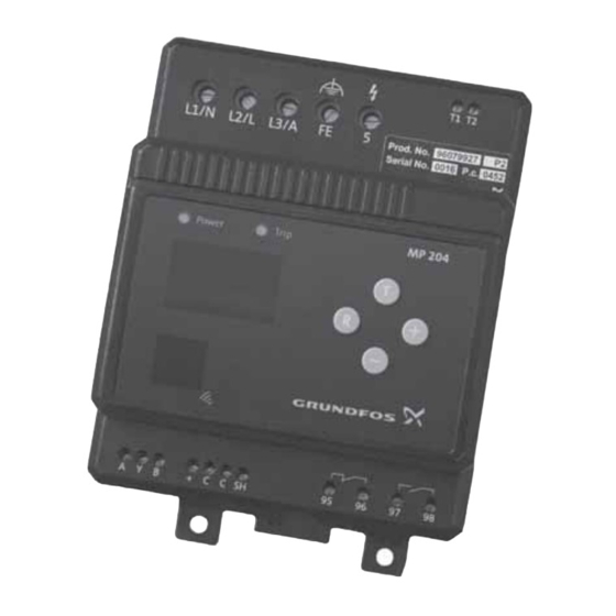
8.1 Overview Pos. 1 Pos. 2 Pos. 3 MP 204 Pos. 7 Pos. 4 Pos. 5 Pos. 6 Fig. 6 Terminals Fig. 5 Cable entries Pos. Designation Three-phase connection Single-phase connection Cable Entry for phase L1 to motor Entry for neutral Max. -
Page 8: Input For Pt100/Pt1000
"5" to MP 204 must be protected separately with maximum 10 A fuses. See fig. 8. If current transformers are used, the L1-L2-L3 and "5" to MP 204 must be protected with maximum 10 A fuses. For installation examples, see figs to 12. -
Page 9: Wiring Diagrams
The connections to L1, L2, L3 and "5" can be made with a cable of up to 10 mm . A special fuse unit up to approximately 50 A is therefore not required. Maximum 10 A MP 204 Pt100 Pt100/Pt1000 Fig. 8 Three-phase connection... - Page 10 8.5.2 Three-phase system with external current transformers Maximum 10 A MP 204 Pt100 Pt100/Pt1000 Fig. 9 Three-phase connection with current transformers Fig. 10 Five windings per phase through MP 204...
- Page 11 8.5.3 Single-phase system with start and run capacitors start MP 204 Pt100/Pt1000 Pt100 Fig. 11 Single-phase connection...
-
Page 12: External Current Transformers
8.6 External current transformers Take the three measuring cables through the three holes in MP 204 five times per phase. See fig. 13. At motor currents above 120 A, external current The three current transformers must be fitted in the transformers must be used. -
Page 13: Startup
9. Startup 9.1.3 Button (+) Normally the actual current or temperature appears A basic setting of MP 204 can be made on the on the display. Press the button to show operating panel. information on the display, according to the following... -
Page 14: Setting On Operating Panel
"P", is normally selected. The time is factory-set to 10 seconds. It can be changed with Grundfos GO Remote. For other pumps, the required IEC trip class (1-45) is to be set. Normally class 10 is selected. For trip curves, see page 20. - Page 15 9.2.4 Number of phases Set the number of phases with the buttons (1 phase, 3 phases (non-earthed) or 3 phases with FE (functional earth)). • Press to store the setting and continue. • Press to store the setting and finish. The programming mode ends automatically after 10 seconds, and the change is stored.
-
Page 16: Learning Function
5 seconds, Control MP 204. while the values are being stored in MP 204. See fig. 14, pos. 3. All variants can be extended with external communication as an option. -
Page 17: Mp 204 With Genibus
• "PTC sensor/thermal switch" • "Restarts per 24 hours" If several MP 204 units are connected to the same GENIbus, the connection is to be made as shown in • "Display units" fig. 18. •... -
Page 18: Pump Operation With Mp 204
Industrial pumps may incorporate a PTC/thermal not installed in the same cable tray. To avoid switch to be connected direct to MP 204. interference, it may be necessary to fit a filter on the Industrial pumps mainly apply IEC trip classes 20 to power cables. -
Page 19: Curves
• Set the trip delay to 900 ms. Figure 20, curve 1:The pump has an abnormal startup time, and the current exceeds 10 A. MP 204 trips after 900 ms. Figure 20, curve 2:The pump has a normal startup time, and the current exceeds 10 A only briefly (<... -
Page 20: Iec Trip Curves
Set MP 204 to IEC trip class 20. • Set the overload limit to 10 A. The rated motor current is stated on the nameplate. At a motor current of 22.5 A (10 x 2.25), MP 204 trips after approximately 170 seconds. -
Page 21: Technical Data
test mains 400 VAC, 2 A, AC-15/24 Example Maximum load VDC, 2 A, DC-13, L/R = MP 204 is connected to 3 x 400 V. 40 ms Minimum load 5 V/10 mA × 400 -- - 327 [V] ... -
Page 22: Measuring Ranges
0-4x10 ± 5 % 1 kWh * The measuring circuit in MP 204 is designed for this range, but MP 204 must only be applied with rated supply voltage 100-480 VAC due to safety and approval requirements. 15.5 Setting ranges... -
Page 23: Fault Finding
Wrong phase sequence Service warning Communication alarm for main system Commanded trip (not in alarm log) Low insulation resistance Too many starts per hour The motor is operating even if MP 204 is tripped Overvoltage Undervoltage Overload Underload Overtemperature, Tempcon measurement... -
Page 24: Fault Finding The Product
L1, L2, L3, etc., and then repeat the and Energy completed. learning function. Consumption. MP 204 display is Checksum in the EERPOM is Reprogram the firmware to MP 204 from not showing FFFF. incorrect. Grundfos PC Tool Water Utility. MP 204 display Internal failure. Replace unit. - Page 25 Appendix Dimensions All dimensions in mm.
- Page 26 Argentina China Hong Kong Bombas GRUNDFOS de Argentina S.A. GRUNDFOS Pumps (Shanghai) Co. Ltd. GRUNDFOS Pumps (Hong Kong) Ltd. Ruta Panamericana km. 37.500 Centro 10F The Hub, No. 33 Suhong Road Unit 1, Ground floor Industrial Garin Minhang District Siu Wai Industrial Centre 1619 Garín Pcia.
- Page 27 Malaysia Serbia Turkey GRUNDFOS Pumps Sdn. Bhd. Grundfos Srbija d.o.o. GRUNDFOS POMPA San. ve Tic. Ltd. 7 Jalan Peguam U1/25 Omladinskih brigada 90b Sti. Glenmarie Industrial Park 11070 Novi Beograd Gebze Organize Sanayi Bölgesi 40150 Shah Alam Phone: +381 11 2258 740...
- Page 28 96650480 0819 ECM: 1261959 www.grundfos.com...
Need help?
Do you have a question about the MP 204 and is the answer not in the manual?
Questions and answers