Advertisement
Table of Contents
Z-PC Line
Z-PC Line
EN
EN
Installation
Installation
Manual
Manual
Contents:
- General Specifications
- Technical Specifications
- Installation Rules
- Electrical connections
- CAN Bus connection rules
- DIP-switches settings
- Programming
- Significant Components Position
- Leds Signallings
- Factory Settings
- Decommissioning and disposal
SENECA s.r.l.
Via Austria, 26 – 35127 – PADOVA – ITALY
Tel. +39.049.8705355 - 8705359 - Fax +39.049.8706287
Manuals and configuration software are available at www.seneca.it
This document is property of SENECA srl. Duplication and reprodution are forbidden, if not authorized.
Contents of the present documentation refers to products and technologies described in it.
All technical data contained in the document may be modified without prior notice. Content of this
documentation is subject to periodical revision.
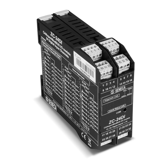
ZC-24DI
ZC-24DI
CANopen/MODBUS I/O Module
CANopen/MODBUS I/O Module
24 Digital Inputs
24 Digital Inputs
MI001515-E
ENGLISH 1/8
Advertisement
Table of Contents

Subscribe to Our Youtube Channel
Related Manuals for Seneca ZC-24DI


Summary of Contents for Seneca ZC-24DI
- Page 1 Tel. +39.049.8705355 - 8705359 - Fax +39.049.8706287 Manuals and configuration software are available at www.seneca.it This document is property of SENECA srl. Duplication and reprodution are forbidden, if not authorized. Contents of the present documentation refers to products and technologies described in it.
-
Page 2: Output
ENERAL SPECIFICATIONS Twentyfour self-powered 16V digital inputs with shared negative pole. Eight inputs settable as 32-bit counters with 10 kHz maximum frequency. Can Interface with CANopen protocol up to 1 Mbps speed or MODBUS RS485 Interface up to 115 Kbit/s speed. ... -
Page 3: Usb Interface
Connections Digital Inputs Removable 4way screw terminals (3.5 mm pitch) Power Supply and CAN/MODBUS Rear IDC10 connector for DIN rail Interface IEC EN 60715 USB interface micro-USB connector (frontal panel) Dimensions / Box Dimensions L: 100 mm; H: 112 mm; W: 35 mm PA6, black Standards Isolations... -
Page 4: Mi001515-E
Power Supply and CAN / MODBUS Interface Power Supply and CAN/MODBUS interface are available by using the bus for the Seneca DIN rail, by the rear IDC10 connector or by Z-PC-DINAL1-35 accessory. GNDCAN / GNDMODBUS Power Supply AC + Rear Connector (IDC10) - Page 5 DIN 15 DIN 23 DIN 8 (Count 8) DIN 16 DIN 24 USB Interface The module has a microUSB connector, you can configure it through APP and/or software. For more information please see www.seneca.it/prod ucts //zc-24di. CU-A-MICROB CU-A-MICROB CU-A-MICRO-OTG ENGLISH 5/8...
-
Page 6: Mi001515-E
DIP-SWITCHES SETTINGS The DIP-switches position defines the module CAN/MODBUS communication parameters: Address and Baud Rate. In the following figure the Baud Rate and Address values are listed as a function of the DIP-switches position: SW1 POSITION CANopen ModBus SW1 POSITION Address Address 1 2 3 4 5 6 7 8 9 10... -
Page 7: Mi001515-E
SIGNIFICANT COMPONENTS POSITION Screw terminals / LED / IDC10 Connector IDC10 / DIP-Switches The screw terminals numbering, the LEDs position on frontal panel, the rear IDC10 connector (for DIN rail connection) and the DIP-Switch on the side are illustrated below. Frontal Panel Side Panel ModBus RTU PROTOCOL:... - Page 8 - Filter active on the 24 Digital inputs / Filter value = 100Hz Variations of standard parameters are possible by EASY SETUP software (please see: www.seneca.it download area). For more information about a list of all register and their function Pease see: USER manual.
Need help?
Do you have a question about the ZC-24DI and is the answer not in the manual?
Questions and answers