Table of Contents
Advertisement
Quick Links
Advertisement
Table of Contents

Related Manuals for Raisecom ISCOM5508-GP

Summary of Contents for Raisecom ISCOM5508-GP
- Page 1 ISCOM5508-GP (A) Hardware Description (Rel_03)
- Page 2 Raisecom Technology Co., Ltd. provides customers with comprehensive technical support and services. For any assistance, please contact our local office or company headquarters. Website: http://www.raisecom.com Tel: 8610-58963399 Fax: 8610-58963399-8886 Email: export@raisecom.com Address: No. 11, East Area, No. 10 Block, East Xibeiwang Rd, Haidian District, Beijing, P.R.China...
- Page 3 Hardware version Software version ISCOM5508-GP A.00 or later V2.61 or later Related manuals The following table lists manuals and their contents related to the ISCOM5508-GP. Name Description ISCOM5508-GP Hardware This guide mainly introduces the hardware structure and Description cards, including product overview, components, fiber and cables, pluggable optical module, lookup table of LEDs, lookup table of weight and power consumption.
- Page 4 Paragraphs in Warning, Caution, Notes, and Tip are in Arial. Boldface Names of files, directories, folders, and users are in boldface. For example, log in as user root. Italic Book titles are in italics. Raisecom Proprietary and Confidential Copyright © Raisecom Technology Co., Ltd.
- Page 5 Added the WDFA4 card. Fixed known bugs. Issue 02 (2016-01-27) Second commercial release Updated configurations of cables. Fixed known bugs. Issue 01 (2013-11-29) Initial commercial release Raisecom Proprietary and Confidential Copyright © Raisecom Technology Co., Ltd.
-
Page 6: Table Of Contents
2.4.2 Panel and slots............................13 2.4.3 Interfaces ............................... 13 2.4.4 LEDs ..............................13 2.4.5 Technical specifications ........................14 2.5 WDFA4 subcard ............................. 14 2.5.1 Introduction ............................14 2.5.2 Panel and slots............................14 Raisecom Proprietary and Confidential Copyright © Raisecom Technology Co., Ltd. - Page 7 3.4.2 Appearance ............................31 3.4.3 Technical specifications ........................31 3.5 AC power cable .............................. 32 3.5.1 Introduction ............................32 3.5.2 Appearance ............................32 3.5.3 Technical specifications ........................33 3.6 Ground cable ..............................34 Raisecom Proprietary and Confidential Copyright © Raisecom Technology Co., Ltd.
- Page 8 5 Lookup table of LEDs......................... 42 6 Lookup table of weight and power consumption ..............44 7 Appendix ............................46 7.1 Terms ................................46 7.2 Acronyms and abbreviations .......................... 47 Raisecom Proprietary and Confidential Copyright © Raisecom Technology Co., Ltd.
- Page 9 Figures Figure 1-1 Appearance of the ISCOM5508-GP chassis ..................2 Figure 1-2 Distribution of slots on the ISCOM5508-GP ..................2 Figure 2-1 Appearance of the main control switching card (GPSC) ..............5 Figure 2-2 Appearance of the GP4A subcard ......................5 Figure 2-3 Appearance of the GE4B subcard ......................
- Page 10 Figure 4-1 1000 Mbit/s SFP optical module ......................37 Figure 4-2 Label of the 1000 Mbit/s SFP optical module ..................38 Figure 4-3 SFP+ optical module .......................... 39 Figure 4-4 PON SFP optical module ........................40 Raisecom Proprietary and Confidential Copyright © Raisecom Technology Co., Ltd.
- Page 11 ISCOM5508-GP (A) Hardware Description Tables Tables Table 1-1 Physical parameters of the ISCOM5508-GP ..................3 Table 2-1 Components of the ISCOM5508-GP ..................... 4 Table 2-2 Items on the hardware information label ....................8 Table 2-3 Interfaces on the GPSC card ........................9 Table 2-4 Parameters of the Console interface .......................
- Page 12 Table 4-7 Technical specifications of the Class C+ optical module ..............41 Table 5-1 LEDs of the ISCOM5508-GP ......................42 Table 6-1 Weight and power consumption of the ISCOM5508-GP ..............44 Raisecom Proprietary and Confidential Copyright © Raisecom Technology Co., Ltd.
-
Page 13: Product Overview
Physical parameters 1.1 Overview The ISCOM5508-GP is a next-generation, small-capacity, 1U, and plug-in Gigabit Passive Optical Network (GPON) Optical Line Terminal (OLT). It is oriented to industrial customers, providing rich features and flexible networking solutions to meet low-density and long- distance requirements for optical fiber access. -
Page 14: Appearance And Slots
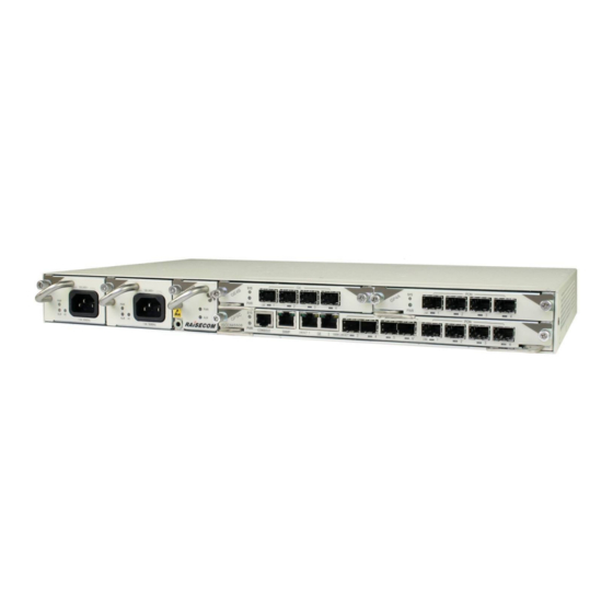
1.2 Appearance and slots 1.2.1 Appearance of chassis The ISCOM5508-GP is a cartridge device, which is flexible to be deployed. Dimensions of the chassis are: 440 mm (Width) × 266 mm (Depth) × 44 mm (Height) (without brackets). Figure 1-1 shows the appearance of the ISCOM5508-GP chassis. -
Page 15: Table 1-1 Physical Parameters Of The Iscom5508-Gp
Raisecom ISCOM5508-GP (A) Hardware Description 1 0BProduct overview Table 1-1 Physical parameters of the ISCOM5508-GP Technical specification Description Dimensions 440 mm (Width) × 266 mm (Depth) × 44 mm (Height) (without brackets) DC: 5.0 kg Weight Standard configuration ... -
Page 16: Components
AC power module (RPA1101-SI-220S12) DC power module (RPD1101-48S12) Fan module (FANS306) 2.1 Overview of components 2.1.1 Classification of components The ISCOM5508-GP is composed of the following four types of components: Main control switching card Extended subcard Power module ... -
Page 17: Appearances Of Components
Figure 2-1 Appearance of the main control switching card (GPSC) Appearance of expansion subcards Figure 2-2 shows the appearance of the GP4A subcard. Figure 2-2 Appearance of the GP4A subcard Figure 2-3 shows the appearance of the GE4B subcard. Raisecom Proprietary and Confidential Copyright © Raisecom Technology Co., Ltd. -
Page 18: Figure 2-3 Appearance Of The Ge4B Subcard
Figure 2-3 Appearance of the GE4B subcard Figure 2-4 Appearance of the WDFA4 subcard Appearance of power module Figure 2-5 shows the appearance of the power module. Figure 2-5 Appearance of the power module Raisecom Proprietary and Confidential Copyright © Raisecom Technology Co., Ltd. -
Page 19: Hardware Information Label
Figure 2-6 Appearance of the fan module 2.1.3 Hardware information label Hardware information of ISCOM5508-GP components will be described by a label pasted on the Printed Circuit Board (PCB) to facilitate you to view it, as shown in Figure 2-7. -
Page 20: Main Control Switching Card (Gpsc)
4 GPON optical interfaces, 2 GE electrical interfaces (RJ45), 2 GE optical interfaces (SFP), and two 10GE optical interfaces (SFP+). Moreover, it supports managing and maintaining the ISCOM5508-GP through the SNMP interface and Console interface. 2.2.2 Panel and slots The GPSC card can be inserted into slot 1 only. -
Page 21: Table 2-3 Interfaces On The Gpsc Card
Table 2-5 lists parameters of the SNMP interface. Table 2-5 Parameters of the SNMP interface Parameter Description Connector RJ45 Interface rate 10/100BASE-T self-adaption Support straight-through and crossover cable self-adaption in host Wiring mode Compliant standard IEEE 802.3 Raisecom Proprietary and Confidential Copyright © Raisecom Technology Co., Ltd. -
Page 22: Leds
Green: the interface is connected properly and no data is being transmitted. (RJ45 electrical Blinking green: the interface is transmitting data. interface Off: the interface is disconnected or connected integrated LED) improperly. Raisecom Proprietary and Confidential Copyright © Raisecom Technology Co., Ltd. -
Page 23: Technical Specifications
Power consumption < 34.5 W 2.3 GP4A subcard 2.3.1 Introduction The GP4A subcard is a PON interface subcard of the ISCOM5508-GP, providing 4 GPON SFP interfaces. 2.3.2 Panel and slots The GP4A subcard can be inserted into slot 3 of the ISCOM5508-GP. -
Page 24: Interfaces
Table 2-11 Technical specifications of the GP4A subcard Item Description Dimensions 129.4 mm (Width) × 243.4 mm (Depth) × 19.8 mm (Height) Weight 0.37 kg Power consumption < 14.5 W Raisecom Proprietary and Confidential Copyright © Raisecom Technology Co., Ltd. -
Page 25: Ge4B Subcard
ISCOM5508-GP (A) Hardware Description 2 1BComponents 2.4 GE4B subcard 2.4.1 Introduction The GE4B subcard is a GE interface subcard of the ISCOM5508-GP, providing 4 SFP GE interfaces. 2.4.2 Panel and slots The GE4B subcard can be inserted into slot 2 or slot 3. -
Page 26: Technical Specifications
2.5 WDFA4 subcard 2.5.1 Introduction The WDFA4 subcard is an EDFA expansion subcard of the ISCOM5508-GP, providing 1 way of CATV service input, 4 ways of OLT data service inputs, 4 ways of wave multiplexing service outputs, and 1 USB interface. -
Page 27: Interfaces
129.4 mm (Width) × 243.4 mm (Depth) × 19.8 mm (Height) Weight 0.55 kg ≤ 20 W Power consumption Table 2-18 lists optical amplification technical specifications of the WDFA4 subcard. Raisecom Proprietary and Confidential Copyright © Raisecom Technology Co., Ltd. -
Page 28: Table 2-18 Optical Amplification Technical Specifications Of The Wdfa4 Subcard
– – – Polarization Dependent Loss – – – Optical Return Loss – – – – – 0.05 – Power tolerance – – – ℃ Others Working Temperature – – Raisecom Proprietary and Confidential Copyright © Raisecom Technology Co., Ltd. -
Page 29: Ac Power Module (Rpa1101-Si-220S12)
– 2.6 AC power module (RPA1101-SI-220S12) 2.6.1 Introduction The RPA1101-SI-220S12 (hereinafter referred to as RPA1101) module is an AC power module of the ISCOM5508-GP. It supports the following features: Wide voltage input: 100–240 VAC Rated output voltage: 12 V; rated output current: 8.3 A ... -
Page 30: Interfaces
Red: the device is powered on improperly. Off: the device is powered off or powered on properly. 2.6.5 Technical specifications Table 2-21 lists technical specifications of the RPA1101 power module. Raisecom Proprietary and Confidential Copyright © Raisecom Technology Co., Ltd. -
Page 31: Dc Power Module (Rpd1101-48S12)
(AC power) 2.7 DC power module (RPD1101-48S12) 2.7.1 Introduction The RPD1101-48S12 (hereinafter referred to as RPD1101) module is a DC power module of the ISCOM5508-GP. It supports the following features: Wide voltage input: -38 to -72 VDC Rated output voltage: 12 V; rated output current: 8.3 A ... -
Page 32: Interfaces
Table 2-24 Technical specifications of the RPD1101 power module Item Description Dimensions 65.6 mm (Width) × 240.6 mm (Depth) × 41.2 mm (Height) Weight 0.49 kg DC power Rated voltage -48 VDC Raisecom Proprietary and Confidential Copyright © Raisecom Technology Co., Ltd. -
Page 33: Fan Module (Fans306)
Output power 100 W 2.8 Fan module (FANS306) 2.8.1 Introduction The FANS306 module is the fan module of the ISCOM5508-GP. It supports the following features: Support fan monitoring. The system monitors the working status of the fan and an alarm is generated when the fan fails. -
Page 34: Technical Specifications
Table 2-26 lists technical specifications of the FANS306 module. Table 2-26 Technical specifications of the FANS306 module Item Description Dimensions 41.9 mm (Width) × 230.1 mm (Depth) × 41.1 mm (Height) Weight 0.3 kg Power consumption Raisecom Proprietary and Confidential Copyright © Raisecom Technology Co., Ltd. -
Page 35: Fiber And Cables
The ISCOM5508-GP supports single-mode fibers and multi-mode fibers, which are different in color. The yellow one is a single-mode fiber and the orange one is a multi-mode fiber. The ISCOM5508-GP can be connected to the Optical Distribution Frame (ODF) or optical interfaces of other devices through fiber. -
Page 36: Connector
Clamping square fiber connector/Curved Blue grinding-and-polishing ferrule end-face LC/APC Clamping square fiber connector/8 degree Green micro-convex grinding-and-polishing ferrule end-face LC/PC fiber connector Figure 3-1 shows the appearance of the LC/PC fiber connector. Raisecom Proprietary and Confidential Copyright © Raisecom Technology Co., Ltd. -
Page 37: Figure 3-1 Lc/Pc Fiber Connector
To remove the fiber, push the fiber head inwards, and then pull the fiber out. FC/PC fiber connector Figure 3-3 shows the appearance of the FC/PC fiber connector. Raisecom Proprietary and Confidential Copyright © Raisecom Technology Co., Ltd. -
Page 38: Wiring
3.2.1 Introduction The Ethernet cable of the ISCOM5508-GP can be used to: Connect the Ethernet electrical interface of the ISCOM5508-GP to other devices. Connect the SNMP of the ISCOM5508-GP to the NView NMS system. Raisecom Proprietary and Confidential... -
Page 39: Appearance
ISCOM5508-GP (A) Hardware Description 3 2BFiber and cables The Ethernet interface on the ISCOM5508-GP is self-adaptive to straight-through cable mode and crossover cable mode. So both kinds of Ethernet cables can be used. The Ethernet cable needs to be made on site. -
Page 40: Figure 3-5 Straight-Through Cable Wiring
PIN 5 White/Blue PIN 5 White/Blue PIN 6 Orange PIN 6 Green PIN 7 White/Brown PIN 7 White/Brown PIN 8 Brown PIN 8 Brown Figure 3-6 shows the crossover cable wiring. Raisecom Proprietary and Confidential Copyright © Raisecom Technology Co., Ltd. -
Page 41: Configuration Cable
CBL-ETH-RJ45/RJ45-2m/RoHS. 3.3 Configuration cable The configuration cable is used to connect the Console interface of the ISCOM5508-GP and the RS-232 serial interface of the maintenance console, and transmit configuration data signals. The maintenance console troubleshoots and maintains the ISCOM5508-GP through the Console interface. -
Page 42: Appearance
Function PIN 1 PIN 6 PIN 2 PIN 7 PIN 3 PIN 8 PIN 4 PIN 9 PIN 5 – – Table 3-8 lists PINs of the RJ45 Ethernet interface. Raisecom Proprietary and Confidential Copyright © Raisecom Technology Co., Ltd. -
Page 43: Dc Power Cable
3.4 DC power cable 3.4.1 Introduction The DC power cable supplies -48 VDC power from the power souring equipment to the power interface on the RPD0601 module of the ISCOM5508-GP, and then transmits power to the entire device. 3.4.2 Appearance The DC power cable is composed of the DC power connector and coaxial cable, as shown in Figure 3-9. -
Page 44: Ac Power Cable
3.5.1 Introduction The AC power cable supplies 110/220 VAC power from the power souring equipment to the power interface on the RPA0601 module of the ISCOM5508-GP, and then transmits power to the entire device. Types of the AC power cable of the ISCOM5508-GP depend on different regional standards, as shown in Table 3-10. -
Page 45: Technical Specifications
White (N), black (L), and yellow strip (E) Conductor 18 AWG/3C gauge Length The letter D indicates the length, which can be customized. For example, if the customer requires 1.5-meter cables, they are named POL-AC-American 3-pin/C13 connector-18AWG-1.5m/RoHS. Raisecom Proprietary and Confidential Copyright © Raisecom Technology Co., Ltd. -
Page 46: Ground Cable
3 2BFiber and cables 3.6 Ground cable Connecting the ground cable properly is an important guarantee for lightning protection, anti-electric shock, and anti-interference. The ISCOM5508-GP must be connected to the ground cable correctly during installation, which helps avoid personal injury and equipment damage. -
Page 47: Technical Specifications
Outer diameter of soldering lug: ≤ 8 mm Inner diameter of sheath: 2.1 mm Thickness of soldering lug: ≥ 0.6 mm Section area of 17–15 AWG (1.2–1.5 mm conducting wire Raisecom Proprietary and Confidential Copyright © Raisecom Technology Co., Ltd. - Page 48 ISCOM5508-GP (A) Hardware Description 3 2BFiber and cables The ISCOM5508-GP is delivered without the ground cable. If required, prepare or make ground cables on site. The ground cable cannot be longer than 30 m and should be as short as possible;...
-
Page 49: Pluggable Optical Modules
ISCOM5508-GP (A) Hardware Description 4 3BPluggable optical modules Pluggable optical modules This chapter describes pluggable optical modules (Raisecom SFP modules are recommended) that could be used by the ISCOM5508-GP, including the following sections: 1000 Mbit/s SFP optical module ... -
Page 50: Technical Specifications
Table 4-2 Technical specifications of the 1000BASE-X SFP optical interface Item Description Connector LC/PC Optical interface properties Depend on the SFP optical module. Working mode Full duplex Compliant standard IEEE 802.3 Supported network protocol Raisecom Proprietary and Confidential Copyright © Raisecom Technology Co., Ltd. -
Page 51: Gbit/S Sfp+ Optical Module
It is integrated with sending and receiving features. Figure 4-3 shows the appearance of the SFP+ optical module. Figure 4-3 SFP+ optical module The 10GE service interface on the ISCOM5508-GP supports the optical module of the following types: ... -
Page 52: Pon Sfp Optical Module
Figure 4-4 shows the appearance of the PON SFP optical module. Figure 4-4 PON SFP optical module 4.3.2 Standard The GPON interface on the ISCOM5508-GP supports the optical module compliant with the Class B+ and Class C+ standard. Raisecom Proprietary and Confidential... -
Page 53: Technical Specifications
Central wavelength (Laser type) Tx: 1490 nm (DFB) Rx: 1310 nm (APD/TIA) Tx optical power 3–7 dBm Extinction ratio 8.2 dB Rx sensitivity -30 dBm Minimum overload point -12 dBm Raisecom Proprietary and Confidential Copyright © Raisecom Technology Co., Ltd. -
Page 54: Lookup Table Of Leds
Raisecom ISCOM5508-GP (A) Hardware Description 5 4BLookup table of LEDs Lookup table of LEDs Table 5-1 lists LEDs of the ISCOM5508-GP. Table 5-1 LEDs of the ISCOM5508-GP Status Description Green Power LED Green: the power supply is working properly. - Page 55 Green: the power module is working properly. Off: the power module is working improperly. Red/Green Power working LED Red: the subcard is working properly. Green: the subcard is working improperly. Raisecom Proprietary and Confidential Copyright © Raisecom Technology Co., Ltd.
-
Page 56: Lookup Table Of Weight And Power Consumption
ISCOM5508-GP (A) Hardware Description 6 5BLookup table of weight and power consumption Lookup table of weight and power consumption Table 6-1 lists weight and power consumption of the ISCOM5508-GP. Table 6-1 Weight and power consumption of the ISCOM5508-GP Component Parameter ... - Page 57 Standard configuration: chassis, main control switching card (GPSC), 2 power modules, and 1 fan module. Full configuration: chassis, main control switching card (GPSC), 2 extended subcards, 2 power modules, and 1 fan module. Raisecom Proprietary and Confidential Copyright © Raisecom Technology Co., Ltd.
-
Page 58: Appendix
ETSI 600 cabinet ETSI standard In a communication link, both parties can receive and send data Full duplex concurrently. Cable to connect device to ground, usually a yellow/green coaxial Ground cable cable Raisecom Proprietary and Confidential Copyright © Raisecom Technology Co., Ltd. -
Page 59: Acronyms And Abbreviations
Self-adaption the result of auto-negotiation. Single-mode In this fiber, single-mode optical signals are transmitted. fiber 7.2 Acronyms and abbreviations American Wire Gauge Access Control List BPDU Bridge Protocol Data Unit Raisecom Proprietary and Confidential Copyright © Raisecom Technology Co., Ltd. - Page 60 Link Layer Discovery Protocol MPLS Multi-protocol label switching Optical Distribution Frame Operation Administration and Maintenance Packet Transport Network Precision Time Protocol Quality of Service Relative Humidity Service-Level Agreement Uninterruptible Power Supply Raisecom Proprietary and Confidential Copyright © Raisecom Technology Co., Ltd.
- Page 61 Address No. 11, East Area, No. 10 Block, East Xibeiwang Rd, Haidian District, Beijing, P.R.China Postal code: 100094 Tel: +86-10-58963399 Fax: 8610-58963399-8886 http://www.raisecom.com Email: export@raisecom.com...
Need help?
Do you have a question about the ISCOM5508-GP and is the answer not in the manual?
Questions and answers