Sign In
Upload
Manuals
Brands
Raisecom Manuals
Touch terminals
ISCOM5508-GP
Raisecom ISCOM5508-GP Manuals
Manuals and User Guides for Raisecom ISCOM5508-GP. We have
2
Raisecom ISCOM5508-GP manuals available for free PDF download: Hardware Description, Installation Manual
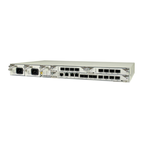
Raisecom ISCOM5508-GP Hardware Description (61 pages)
Brand:
Raisecom
| Category:
Touch terminals
| Size: 1 MB
Table of Contents
Table of Contents
6
1 Product Overview
13
Overview
13
Appearance and Slots
14
Appearance of Chassis
14
Distribution of Slots
14
Physical Parameters
14
Figure 1-1 Appearance of the ISCOM5508-GP Chassis
14
Figure 1-2 Distribution of Slots on the ISCOM5508-GP
14
Table 1-1 Physical Parameters of the ISCOM5508-GP
15
2 Components
16
Overview of Components
16
Classification of Components
16
Table 2-1 Components of the ISCOM5508-GP
16
Appearances of Components
17
Figure 2-1 Appearance of the Main Control Switching Card (GPSC)
17
Figure 2-2 Appearance of the GP4A Subcard
17
Figure 2-3 Appearance of the GE4B Subcard
18
Figure 2-4 Appearance of the WDFA4 Subcard
18
Figure 2-5 Appearance of the Power Module
18
Hardware Information Label
19
Figure 2-6 Appearance of the Fan Module
19
Figure 2-7 Hardware Information Label on the ISCOM5508-GP
19
Main Control Switching Card (GPSC)
20
Introduction
20
Panel and Slots
20
Interfaces
20
Figure 2-8 Panel of the GPSC Card
20
Table 2-2 Items on the Hardware Information Label
20
Table 2-3 Interfaces on the GPSC Card
21
Table 2-4 Parameters of the Console Interface
21
Table 2-5 Parameters of the SNMP Interface
21
Leds
22
Table 2-6 Parameters of the GE Interface Based on 10/100/1000BASE-T Standard
22
Table 2-7 Leds on the GPSC Card
22
Technical Specifications
23
GP4A Subcard
23
Introduction
23
Panel and Slots
23
Figure 2-9 Panel of the GP4A Subcard
23
Table 2-8 Technical Specifications of the GPSC Card
23
Interfaces
24
Leds
24
Technical Specifications
24
Table 2-9 Interfaces on the GP4A Subcard
24
Table 2-10 Leds on the GP4A Subcard
24
Table 2-11 Technical Specifications of the GP4A Subcard
24
GE4B Subcard
25
Introduction
25
Panel and Slots
25
Interfaces
25
Leds
25
Figure 2-10 Panel of the GE4B Subcard
25
Table 2-12 Interfaces on the GE4B Subcard
25
Table 2-13 Leds on the GE4B Subcard
25
Technical Specifications
26
WDFA4 Subcard
26
Introduction
26
Panel and Slots
26
Figure 2-11 Panel of the WDFA4 Subcard
26
Table 2-14 Technical Specifications of the GE4B Subcard
26
Interfaces
27
Leds
27
Technical Specifications
27
Table 2-15 Interfaces on the WDFA4 Subcard
27
Table 2-16 LED on the WDFA4 Subcard
27
Table 2-17 Physical Technical Specifications of the WDFA4 Subcard
27
Table 2-18 Optical Amplification Technical Specifications of the WDFA4 Subcard
28
AC Power Module (RPA1101-SI-220S12)
29
Introduction
29
Panel and Slots
29
Interfaces
30
Leds
30
Technical Specifications
30
Figure 2-12 Panel of the RPA1101 Power Module
30
Table 2-19 Interface on the RPA1101 Power Module
30
Table 2-20 Leds on the RPA1101 Power Module
30
DC Power Module (RPD1101-48S12)
31
Introduction
31
Panel and Slots
31
Figure 2-13 Panel of the RPD1101 Power Module
31
Table 2-21 Technical Specifications of the RPA1101 Power Module
31
Interfaces
32
Leds
32
Technical Specifications
32
Table 2-22 Interface on the RPD1101 Power Module
32
Table 2-23 Leds on the RPD1101 Power Module
32
Table 2-24 Technical Specifications of the RPD1101 Power Module
32
Fan Module (FANS306)
33
Introduction
33
Panel and Slots
33
Leds
33
Figure 2-14 Panel of the FANS306 Module
33
Technical Specifications
34
Table 2-25 Leds on the FANS306 Module
34
Table 2-26 Technical Specifications of the FANS306 Module
34
3 Fiber and Cables
35
Fiber
35
Introduction
35
Table 3-1 Type and Usage of the Fiber
35
Connector
36
Table 3-2 Fiber Connectors
36
Figure 3-1 LC/PC Fiber Connector
37
Figure 3-2 SC/PC Fiber Connector
37
Wiring
38
Ethernet Cable
38
Introduction
38
Figure 3-3 FC/PC Fiber Connector
38
Table 3-3 Wiring of the Fiber
38
Appearance
39
Technical Specifications
39
Figure 3-4 Ethernet Cable
39
Table 3-4 PIN Definitions of the Straight-Through Cable
39
Figure 3-5 Straight-Through Cable Wiring
40
Table 3-5 PIN Definitions of the Crossover Cable
40
Configuration Cable
41
Figure 3-6 Crossover Cable Wiring
41
Table 3-6 Technical Specifications of the Ethernet Cable
41
Appearance
42
Figure 3-7 Configuration Cable
42
Figure 3-8 Pins and Wiring
42
Table 3-7 Pins of the RS-232 Interface
42
Wiring
42
DC Power Cable
43
Introduction
43
Appearance
43
Technical Specifications
43
Figure 3-9 DC Power Cable
43
Table 3-8 Pins of the RJ45 Ethernet Interface
43
Table 3-9 Technical Specifications of the DC Power Cable
43
AC Power Cable
44
Introduction
44
Appearance
44
Figure 3-10 European AC Power Cable
44
Figure 3-11 American AC Power Cable
44
Table 3-10 AC Power Cable
44
Technical Specifications
45
Table 3-11 Technical Specifications of the European AC Power Cable
45
Table 3-12 Technical Specifications of the American AC Power Cable
45
Ground Cable
46
Introduction
46
Appearance
46
Figure 3-12 Ground Cable
46
Figure 3-13 OT Terminal
46
Technical Specifications
47
Table 3-13 Technical Specifications of the Ground Cable
47
Table 3-14 Technical Specifications of the OT Terminal
47
4 Pluggable Optical Modules
49
1000 Mbit/S SFP Optical Module
49
Functions and Appearance
49
Label
49
Figure 4-1 1000 Mbit/S SFP Optical Module
49
Technical Specifications
50
Figure 4-2 Label of the 1000 Mbit/S SFP Optical Module
50
Table 4-1 Model of the 1000 Mbit/S SFP Optical Module
50
Table 4-2 Technical Specifications of the 1000BASE-X SFP Optical Interface
50
Gbit/S SFP+ Optical Module
51
Functions and Appearance
51
Technical Specifications
51
Figure 4-3 SFP+ Optical Module
51
Table 4-3 Technical Specifications of the 1000BASE-X SFP Optical Module
51
PON SFP Optical Module
52
Functions and Appearance
52
Standard
52
Figure 4-4 PON SFP Optical Module
52
Table 4-4 Technical Specifications of the SFP+ Optical Interface
52
Table 4-5 Technical Specifications of the SFP+ Optical Module
52
Technical Specifications
53
Table 4-6 Technical Specifications of the Class B+ Optical Module
53
Table 4-7 Technical Specifications of the Class C+ Optical Module
53
5 Lookup Table of Leds
54
Table 5-1 Leds of the ISCOM5508-GP
54
6 Lookup Table of Weight and Power Consumption
56
Table 6-1 Weight and Power Consumption of the ISCOM5508-GP
56
7 Appendix
58
Terms
58
Acronyms and Abbreviations
59
Advertisement
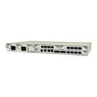
Raisecom ISCOM5508-GP Installation Manual (60 pages)
Brand:
Raisecom
| Category:
Network Hardware
| Size: 2 MB
Table of Contents
Symbol Conventions
3
General Conventions
4
Command Conventions
4
GUI Conventions
4
Keyboard Operation
5
Mouse Operation
5
Change History
5
Table of Contents
6
Safety Instruction
12
Safety Statement
12
Safety Symbols
12
Electrical Safety
13
High Voltage Safety
13
Power Cable Safety
13
Table 1-1 Types and Meanings for Safety Symbols
13
Thunder-And-Lightning Safety
14
Electrostatic Safety
14
Radiation Safety
14
Electromagnetic Exposure Safety
14
Laser Safety
15
Mechanical Safety
15
Drilling
15
Carrying Chassis
16
Others
16
Inserting and Removing Cards
16
Laying down Cables
16
Replacing Components
16
Preparing for Installation
17
Preparing Tools and Instruments
17
Table 2-1 Tools and Instruments for Preparation
17
Checking Installation Conditions
19
Installation Environment
19
Table 2-2 Working Environment Parameters
19
Power Conditions
20
Grounding Conditions
20
Other Conditions
20
Checking Boxes
20
Table 2-3 Power Conditions
20
Checking Box before Unpacking
21
Unpacking Chassis
21
Figure 2-1 Unpacking Chassis
21
Upacking Components
22
Figure 2-2 Unpacking Components
22
Acceptance Inspection
23
Installing Chassis
24
Installation Process
24
Check before Installation
25
Figure 3-1 Installation Process
25
Installing Chassis
26
Introduction
26
Installing Chassis in Cabinet
26
Figure 3-2 Installing Floating Nuts
27
Figure 3-3 Installing Standard Brackets on the Left Side of the Chassis
27
Figure 3-4 Installing Standard Brackets on the Right Side of the Chassis
28
Figure 3-5 Installing Chassis in Cabinet
28
Installing Chassis on Workbench
29
Figure 3-6 Cleaning Chassis Bottom
29
Connecting Ground Cable
30
Figure 3-7 Sticking Rubber Feet
30
Figure 3-8 Installing Chassis on Workbench
30
Figure 3-9 Ground Cable
30
Figure 3-10 Location of Ground Terminals
31
Figure 3-11 Connecting the Ground Cable
31
Figure 3-12 Grounding Chassis
32
Installing Components
33
Anti-Static Preparation
33
Figure 4-1 ESD Wrist Strap
33
Installing Components
34
Figure 4-2 ESD Wrist Strap
34
Figure 4-3 Installing Components
34
Removing Components
35
Figure 4-4 Tightening Screws
35
Figure 4-5 Loosening Captive Screws
36
Figure 4-6 Pulling the Ejector Levers Outward
36
Figure 4-7 Pulling Components Outward
36
Connecting Cables
37
Connecting DC Power Cable
37
Figure 5-1 Inserting Plug into DC Outlet
37
Connecting AC Power Cables
38
Figure 5-2 Tightening Captive Screws on DC Power Connector
38
Figure 5-3 Connecting AC Power Cable
38
Connecting Ethernet Cables
39
Figure 5-4 Connecting Ethernet Cable
39
Connecting Optical Fibers
40
Figure 5-5 Inserting SFP Optical Module
40
Connecting Configuration Cables
41
Figure 5-6 Connecting Optical Connectors
41
Figure 5-7 Connecting Configuration Cable
41
Checking Hardware Installation
42
Checking Machine Room and the Surrounding Environment
42
Checking Cabinet or Workbench
42
Table 6-1 Checklist of the Machine Room and Surrounding Environment
42
Checking Chassis and Cards
43
Checking Cables
43
Table 6-2 Checklist of Cabinet or Workbench
43
Table 6-3 Checklist of Chassis and Card
43
Table 6-4 Checklist of Cables
44
Power-On Test
45
Precautions
45
Powering on Device
45
Table 7-1 Power-On Test
45
Running Check
46
Installation Reference
47
Tail Fiber Binding Tape
47
The Structure of Tail Fiber Binding Tape
47
The Clipping of Tail Fiber Binding Tape
47
Figure 8-1 Tail Fiber Binding Tape
47
Use of Tail Fiber Binding Tape
48
Figure 8-2 the Clipping of Binding Tape
48
Figure 8-3 the Clipping of Tail Fiber Binding Tape
48
Precautions
49
Figure 8-4 Tail Fiber Binding Tape
49
Figure 8-5 Finished Effect
49
Cable Label Specifications
50
Overview of Label
50
Label Filling
50
Figure 8-6 Cable Label
50
Method to Stick Labels
51
Figure 8-7 Writing Direction of Label Content
51
Figure 8-8 Directions of Label Text Area
51
Table 8-1 Standard Font Template
51
Project Label of Network Cable
52
Figure 8-9 Label Sticking Process
52
Figure 8-10 Network Cable Label
52
Table 8-2 Project Label Writing Content of Network Cable
52
Project Label of Optical Fiber
53
Table 8-3 Meaning of Fiber Labels between Devices
53
Figure 8-11 Fiber Label between Devices
54
Table 8-4 the Meaning of Fiber Labels from Device to ODF
54
Project Label of DC Power Cable
55
Figure 8-12 Fiber Label from Device to ODF
55
Table 8-5 the Label Meaning of DC Power Cable
55
Figure 8-13 DC Power Cable Label
56
Project Label of AC Power Cable
57
Figure 8-14 AC Power Cable Label
57
Table 8-6 the Label Meaning of AC Power Cable
57
Introduction and Usage of Ribbon
58
Figure 8-15 Plastic Belt
58
Figure 8-16 Binding Cables with Ribbon
58
Figure 8-17 Binding Effect
59
Advertisement
Related Products
Raisecom ISCOM6820-GP
Raisecom ISCOM5508
Raisecom ISCOM5504-GP
Raisecom ISCOM5508-GPA
Raisecom ISCOM2624G-4C
Raisecom ISCOM2608G-2GE-PWR-AC
Raisecom ISCOM2648G-4GE-DC
Raisecom ISCOM3012GF
Raisecom ISCOM2600-28X-AC
Raisecom ISCOM2624G-4GE-AC
Raisecom Categories
Multiplexer
Switch
Network Hardware
Media Converter
Network Router
More Raisecom Manuals
Login
Sign In
OR
Sign in with Facebook
Sign in with Google
Upload manual
Upload from disk
Upload from URL