
Related Manuals for rotork RH Series


Summary of Contents for rotork RH Series
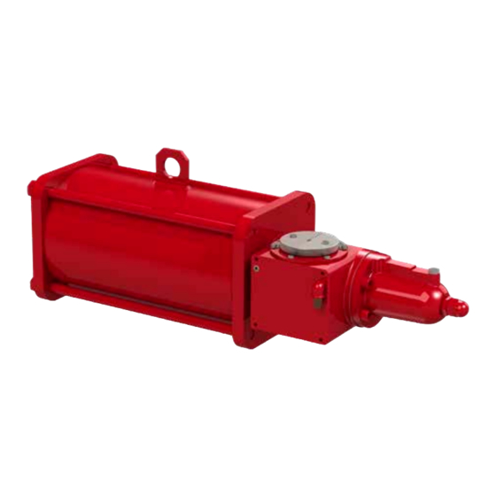
- Page 1 Range Hydraulic Actuator Single-Acting and Double-Acting Configuration Installation, Commissioning and Maintenance Manual...
-
Page 2: Table Of Contents
This manual contains important safety information. Please ensure it is throughly read and understood before installing, operating or maintaining the equipment. Rotork reserves the right to modify, amend and improve this manual without notice. Due to wide variation in the terminal numbering of... -
Page 3: Introduction
UNI EN ISO 7010: Safety Signals Customer Service For technical assistance, please contact Rotork Customer Service: E-mail: rfs.internationalservice@rotork.com Rotork Fluid Systems, Porcari, Lucca, IT tel: +39 39 (0)583 222 1 Rotork plc, Brassmill Lane, Bath, UK. Tel +44 (0)1225 733200... -
Page 4: General Information
Health & Safety This manual is produced to enable a competent user to install, Before installing the equipment, verify it is suitable for the operate and maintain Rotork RH single and double-acting intended application. If unsure consult Rotork. actuators. Residual Risks... -
Page 5: Magnetic Risks
The following label is applied externally to the actuator: dismantling. Preventive measures Do not disassemble the actuator during dismantling. Follow instructions in the present manual and contact Rotork. Magnetic Risks Risk Risk of magnetic field/disturbance and exothermic reactions. Preventive measure... -
Page 6: Operating Limits
Operating Limits Tightening Torque Chart Temperature: -30 to +100 °C (-22 to +212 °F) for standard applications RECOMMENDED TIGHTENING TORQUE -20 to +100 °C (-4 to +212 °F) for PED (Class 8.8 bolts) applications -40 to +100 °C (-40 to +212 °F) for low Bolt Size Ft. -
Page 7: Handling & Lifting
Handling & Lifting Only trained and experienced personnel should • Angle β must be between 0° and 45° as shown below. handle/lift the actuator. The actuator is supplied packed on pallets suitable for normal handling. Handle the actuator with care. Never stack pallets. Direction Lifting Recommendations of Pull... - Page 8 Handling & Lifting Fig 7.2 Lifting double-acting RH body sizes 015, 030, Fig 7.3 Lifting double-acting RH body sizes 090, 105, 060, 120, 240. 125, 145, 155, 185, 225, 250, 280. RH Range Installation, Commissioning and Maintenance Manual...
-
Page 9: Storage
Storage Long Term Storage Rotork actuators have been fully tested before leaving If long term storage is necessary, further operations must the factory. be carried out to maintain the actuator in a good working condition: Actuators must be kept in good condition until installation. -
Page 10: Installation On Valve
TAG numbers. position Consult Rotork for any additional information. • If the assembly is done using an adapter and a coupling joint, assemble the coupling joint onto the valve stem 10.1 Preliminary Actions... -
Page 11: Removal From Valve
Removal shall be performed only by qualified staff, wearing/using appropriate personal protection equipment. Do not remove the actuator if the valve is blocked in the intermediate position. Contact Rotork Customer Service. To disassemble the actuator from the valve, proceed as follows: •... -
Page 12: Operation
The following instructions must be integrated into the user Upon request, RH/S actuators can be equipped with safety program when installing and using Rotork products. additional accessories (limit switches box, positioner, position Read and save all instructions prior to installing, operating transmitter, control panel, etc.). - Page 13 • Two mechanical stop bolts to enable adjustment of valve angular stroke. Only use control devices supplied by Rotork. • A mechanical visual position indicator directly connected to the valve stem that shows position of the valve through full actuator stroke.
-
Page 14: Operating Description
C0 ÷ C9 = Spring-Return Fail Close - Certain valves incorporate their own travel stops. Spring set # 0-9 Rotork recommend the actuator stop bolt positions O0 ÷ O9 = Spring-Return Fail Open - match the valve stop positions. Spring set # 0-9... - Page 15 Operation 12.5.1 Single-acting actuator RH/S (body sizes 015, 030, 060, 120, 240), cylinder stop bolt setting Set the cylinder stop bolt first. Where shown, tools may be required. J. Re-position the seal washer (2) between the cylinder and the stop nut (4) Adjust the stop bolt in the end flange of the cylinder as follows: A.
- Page 16 Operation 12.5.2 Single-acting actuator RH/S (body sizes 015, 030, 060, 120, 240), spring cartridge stop bolt setting Where shown, tools may be required. Adjust the stop bolt in the spring cartridge as follows: Hold the stop bolt (8) and carefully tighten the stop nut (7) J.
- Page 17 Operation 12.5.4 Double-acting actuator RH/D4 (body sizes 090, 105, 125, 145, 155, 185, 225, 250, 280), cylinder stop bolt setting Set the cylinder stop bolts first. Instructions assume operating direction is in accordance with conventions detailed in ISO 5211. Clockwise to close and anticlockwise to open.
-
Page 18: Hydraulic Power Supply
Operation 12.6 Hydraulic Power Supply Inlet port Check the supply pressure range on actuator label. Verify medium composition. Contact Rotork to check the compatibility with the supply medium. 12.7 Hydraulic Connections Preliminary Operations A. Confirm the size of pipes and fittings per applicable plant specifications Fig 12.12 Inlet port for single-acting actuator RH/S... -
Page 19: Electrical Connections
Operation 12.8 Electrical Connections 12.9 Start Up Check supply voltage of electrical components. Check the following during start-up of the actuator: • Medium supply pressure is correct Access to live electrical conductors is forbidden in hazardous areas unless done under a special permit. All •... -
Page 20: Dismantling And Disposal
Should you require technical assistance or spares, Rotork depressurised before dismantling can begin. guarantees the best service in the world. Contact your local Rotork representative or the factory direct at the address on For single-acting actuators. the nameplate, quoting the actuator type and serial number. -
Page 21: Troubleshooting
Inadequate supply pressure and that the output torque produced at supply Loss of power pressure exceeds the required valve torque. • Replace seals according instructions reported in • Leakage from cylinder PM-RH-006 or PM-RH-007 For other problems, please contact Rotork Customer Service. -
Page 22: Periodic Maintenance
Periodic Maintenance Rotork recommends performing the following checks to help comply with the rules and regulations of the country of final installation: Remove pressure before proceeding with maintenance operations, discharge any accumulators or tanks (if present), except where otherwise indicated. - Page 23 Periodic Maintenance PM-RH-001 Page: 1/1 Component: Single-acting actuator Task: Cleaning Double-acting actuator Equipment, Tools, Materials: Warnings: Air compressor Project documentation (Design and Operating pressure values) Damp Cloth Preliminary Operations: Description: Remove hydraulic power supply and electric power supply (if present) before proceeding. 1.
- Page 24 Periodic Maintenance PM-RH-002 Page: 1/1 Component: Single-acting actuator Task: Functional test Double-acting actuator Equipment, Tools, Materials: Warnings: Chronometer Project documentation (required stroke times) Preliminary Operations: Description: NOTE: Actuator must be connected to the hydraulic supply to perform the following test. 1.
- Page 25 Periodic Maintenance PM-RH-003 Page: 1/1 Component: Mechanical Manual Override for RH/S and RH/D2 - Task: Manual override functional test body sizes 015, 030, 060, 120, 240 Equipment, Tools, Materials: Warnings: Project documentation Preliminary Operations: Description: Opening operation 1. Verify the absence of pressure 2.
- Page 26 Periodic Maintenance PM-RH-004 Page: 1/1 Component: Electrical components (if present) Task: Check electrical components (if present) and grounding connections Equipment, Tools, Materials: Warnings: Project documentation Preliminary Operations: Description: Isolate electric power supply before working on electrical devices. Read and follow the safety precautions in the component manufacturer’s maintenance manual. Risk of temporary modification to component protection.
- Page 27 Periodic Maintenance PM-RH-005a Page: 1/1 Component: Hydraulic manual override for single-acting actuator Task: Single-acting actuator RH/S hand pump hydraulic oil replacement RH/S – body sizes 015, 030, 060, 120, 240 Equipment, Tools, Materials: Warnings: Project documentation Wrench Preliminary Operations: Description: Tasks must be executed with the tank in the vertical position and the actuator in the fail position.
- Page 28 Periodic Maintenance PM-RH-005b Page: 1/1 Component: Hydraulic manual override for double-acting actuator Task: Double-acting actuator RH/D2 hand pump hydraulic oil RH/D2 – body sizes 015, 030, 060, 120, 240 replacement Equipment, Tools, Materials: Warnings: Project documentation Wrench Preliminary Operations: Description: Tasks must be executed with the tank in the vertical position and the actuator in the fail position.
- Page 29 Periodic Maintenance PM-RH-006 Page: 1/10 Component: Single-acting actuator RH/S and double-acting actuator Task: Hydraulic cylinder and centre body seal replacement RH/D2 – body sizes 015, 030, 060, 120, 240 Equipment, Tools, Materials: Warnings: Spare seals Wrench Lifting tools Project documentation Preliminary Operations: Removal from Valve Description: Isolate the hydraulic power supply and electric power supply (if present) before performing any operations.
- Page 30 Periodic Maintenance PM-RH-006 Page: 2/10 Component: Single-acting actuator RH/S and double-acting actuator Task: Hydraulic cylinder and centre body seal replacement RH/D2 – body sizes 015, 030, 060, 120, 240 Equipment, Tools, Materials: Warnings: Spare seals Wrench Lifting tools Project documentation Preliminary Operations: Removal from Valve 8.
- Page 31 Periodic Maintenance PM-RH-006 Page: 3/10 Component: Single-acting actuator RH/S and double-acting actuator Task: Hydraulic cylinder and centre body seal replacement RH/D2 – body sizes 015, 030, 060, 120, 240 Equipment, Tools, Materials: Warnings: Spare seals Wrench Lifting tools Project documentation Preliminary Operations: Removal from Valve 12.
- Page 32 Periodic Maintenance PM-RH-006 Page: 4/10 Component: Single-acting actuator RH/S and double-acting actuator Task: Hydraulic cylinder and centre body seal replacement RH/D2 – body sizes 015, 030, 060, 120, 240 Equipment, Tools, Materials: Warnings: Spare seals Wrench Lifting tools Project documentation Preliminary Operations: Removal from Valve 17.
- Page 33 Periodic Maintenance PM-RH-006 Page: 5/10 Component: Single-acting actuator RH/S and double-acting actuator Task: Hydraulic cylinder and centre body seal replacement RH/D2 – body sizes 015, 030, 060, 120, 240 Equipment, Tools, Materials: Warnings: Spare seals Wrench Lifting tools Project documentation Preliminary Operations: Removal from Valve 21.
- Page 34 Periodic Maintenance PM-RH-006 Page: 6/10 Component: Single-acting actuator RH/S and double-acting actuator Task: Hydraulic cylinder and centre body seal replacement RH/D2 – body sizes 015, 030, 060, 120, 240 Equipment, Tools, Materials: Warnings: Spare seals Wrench Lifting tools Project documentation Preliminary Operations: Removal from Valve 23.
- Page 35 Periodic Maintenance PM-RH-006 Page: 7/10 Component: Single-acting actuator RH/S and double-acting actuator Task: Hydraulic cylinder and centre body seal replacement RH/D2 – body sizes 015, 030, 060, 120, 240 Equipment, Tools, Materials: Warnings: Spare seals Wrench Lifting tools Project documentation Preliminary Operations: Removal from Valve 25.
- Page 36 Periodic Maintenance PM-RH-006 Page: 8/10 Component: Single-acting actuator RH/S and double-acting actuator Task: Hydraulic cylinder and centre body seal replacement RH/D2 – body sizes 015, 030, 060, 120, 240 Equipment, Tools, Materials: Warnings: Spare seals Wrench Lifting tools Project documentation Preliminary Operations: Removal from Valve 27.
- Page 37 Periodic Maintenance PM-RH-006 Page: 9/10 Component: Single-acting actuator RH/S and double-acting actuator Task: Hydraulic cylinder and centre body seal replacement RH/D2 – body sizes 015, 030, 060, 120, 240 Equipment, Tools, Materials: Warnings: Spare seals Wrench Lifting tools Project documentation Preliminary Operations: Removal from Valve 32.
- Page 38 Periodic Maintenance PM-RH-006 Page: 10/10 Component: Single-acting actuator RH/S and double-acting actuator Task: Hydraulic cylinder and centre body seal replacement RH/D2 – body sizes 015, 030, 060, 120, 240 Equipment, Tools, Materials: Warnings: Spare seals Wrench Lifting tools Project documentation Preliminary Operations: Removal from Valve 38.
- Page 39 Periodic Maintenance PM-RH-007 Page: 1/12 Component: Double-acting actuator RH/D4 – body sizes 090, 105, 125, Task: Hydraulic cylinder and centre body seal replacement 145, 155, 185, 225, 250, 280 Equipment, Tools, Materials: Warnings: Spare seals Wrench Lifting tools Project documentation Preliminary Operations: Removal from Valve Description: Isolate the hydraulic power supply and electric power supply (if present) before performing any operations.
- Page 40 Periodic Maintenance PM-RH-007 Page: 2/12 Component: Double-acting actuator RH/D4 – body sizes 090, 105, 125, Task: Hydraulic cylinder and centre body seal replacement 145, 155, 185, 225, 250, 280 Equipment, Tools, Materials: Warnings: Spare seals Wrench Lifting tools Project documentation Preliminary Operations: Removal from Valve 10.
- Page 41 Periodic Maintenance PM-RH-007 Page: 3/12 Component: Double-acting actuator RH/D4 – body sizes 090, 105, 125, Task: Hydraulic cylinder and centre body seal replacement 145, 155, 185, 225, 250, 280 Equipment, Tools, Materials: Warnings: Spare seals Wrench Lifting tools Project documentation Preliminary Operations: Removal from Valve 14.
- Page 42 Periodic Maintenance PM-RH-007 Page: 4/12 Component: Double-acting actuator RH/D4 – body sizes 090, 105, 125, Task: Hydraulic cylinder and centre body seal replacement 145, 155, 185, 225, 250, 280 Equipment, Tools, Materials: Warnings: Spare seals Wrench Lifting tools Project documentation Preliminary Operations: Removal from Valve 17.
- Page 43 Periodic Maintenance PM-RH-007 Page: 5/12 Component: Double-acting actuator RH/D4 – body sizes 090, 105, 125, Task: Hydraulic cylinder and centre body seal replacement 145, 155, 185, 225, 250, 280 Equipment, Tools, Materials: Warnings: Spare seals Wrench Lifting tools Project documentation Preliminary Operations: Removal from Valve 22.
- Page 44 Periodic Maintenance PM-RH-007 Page: 6/12 Component: Double-acting actuator RH/D4 – body sizes 090, 105, 125, Task: Hydraulic cylinder and centre body seal replacement 145, 155, 185, 225, 250, 280 Equipment, Tools, Materials: Warnings: Spare seals Wrench Lifting tools Project documentation Preliminary Operations: Removal from Valve 24.
- Page 45 Periodic Maintenance PM-RH-007 Page: 7/12 Component: Double-acting actuator RH/D4 – body sizes 090, 105, 125, Task: Hydraulic cylinder and centre body seal replacement 145, 155, 185, 225, 250, 280 Equipment, Tools, Materials: Warnings: Spare seals Wrench Lifting tools Project documentation Preliminary Operations: Removal from Valve 29.
- Page 46 Periodic Maintenance PM-RH-007 Page: 8/12 Component: Double-acting actuator RH/D4 – body sizes 090, 105, 125, Task: Hydraulic cylinder and centre body seal replacement 145, 155, 185, 225, 250, 280 Equipment, Tools, Materials: Warnings: Spare seals Wrench Lifting tools Project documentation Preliminary Operations: Removal from Valve 34.
- Page 47 Periodic Maintenance PM-RH-007 Page: 9/12 Component: Double-acting actuator RH/D4 – body sizes 090, 105, 125, Task: Hydraulic cylinder and centre body seal replacement 145, 155, 185, 225, 250, 280 Equipment, Tools, Materials: Warnings: Spare seals Wrench Lifting tools Project documentation Preliminary Operations: Removal from Valve 36.
- Page 48 Periodic Maintenance PM-RH-007 Page: 10/12 Component: Double-acting actuator RH/D4 – body sizes 090, 105, 125, Task: Hydraulic cylinder and centre body seal replacement 145, 155, 185, 225, 250, 280 Equipment, Tools, Materials: Warnings: Spare seals Wrench Lifting tools Project documentation Preliminary Operations: Removal from Valve 41.
- Page 49 Periodic Maintenance PM-RH-007 Page: 11/12 Component: Double-acting actuator RH/D4 – body sizes 090, 105, 125, Task: Hydraulic cylinder and centre body seal replacement 145, 155, 185, 225, 250, 280 Equipment, Tools, Materials: Warnings: Spare seals Wrench Lifting tools Project documentation Preliminary Operations: Removal from Valve 44.
- Page 50 Periodic Maintenance PM-RH-007 Page: 12/12 Component: Double-acting actuator RH/D4 – body sizes 090, 105, 125, Task: Hydraulic cylinder and centre body seal replacement 145, 155, 185, 225, 250, 280 Equipment, Tools, Materials: Warnings: Spare seals Wrench Lifting tools Project documentation Preliminary Operations: Removal from Valve 48.
-
Page 51: Part List
Part List RH/S ACTUATOR– center body sizes 015, 030, 060, 120, 240 Fig 17.1 RH Single-acting actuator ITEM DESCRIPTION ITEM DESCRIPTION Centre body Spring container end flange ● Rack Spring cartridge Rack bushing Seal washer Pinion Stop nut Position indicator seal Stop bolt ●... - Page 52 Part List RH/D2 ACTUATOR – center body sizes 015, 030, 060, 120, 240 Fig 17.2 RH/D2 double-acting (2 cylinders) actuator ITEM DESCRIPTION ITEM DESCRIPTION Stop bolt Pinion retaining flange Seal washer Upper bushing O-ring Lower bushing ● Position indicator seal Pinion ●...
- Page 53 Part List RH/D4 ACTUATOR – Center body - sizes 090, 105, 125, 145, 155, 185, 225, 250, 280 Fig 17.3 Centre body RH/D4 double-acting (4 cylinders actuator) ITEM DESCRIPTION ITEM DESCRIPTION Washer Washer Seal Bushing retaining flange (back) ● Sliding ring Position indicator Bushing Pinion retaining flange...
- Page 54 Part List RH/D4 ACTUATOR Center body sizes 090, 105, 125, 145, 155, 185, 225, 250, 280 – Hydraulic cylinder Fig 17.4 Hydraulic cylinder RH/D4 double-acting (4 cylinders) actuator ITEM DESCRIPTION ITEM DESCRIPTION Plug Piston O-Ring Piston Seal ● ● O-Ring Sliding ring ●...
-
Page 55: Grease & Hydraulic Oil Specification
In general, there is no need to lubricate the actuator because its mechanism is lubricated -for life. The standard grease for Rotork scotch yoke actuators are shown below. If an alternative was specified and/or supplied, please refer to the job specific documentation. -
Page 56: Hydraulic Oil
Grease & Hydraulic Oil Specification 18.2 Hydraulic Oil This is the standard oil specification for hydraulic cylinders working at temperature between -20 and +100 °C for ATEX and non-ATEX application. Manufacturer: MOBIL Trade Name: DTE 10 EXCEL 32 ISO Viscosity Grade: Viscosity, ASTM D 445 cSt @ 40 °C 32.7... - Page 57 Grease & Hydraulic Oil Specification This is the standard oil specification for hydraulic cylinders working at temperature down to -60 °C for non-ATEX applications. Manufacturer: MOBIL Trade Name: UNIVIS HVI ISO Viscosity Grade: Viscosity, ASTM D 445 cSt @ 40 °C 13.5 cSt @ 100 °C Viscosity Index, ASTM D 2270...
- Page 58 +44 (0)1225 733200 email mail@rotork.com All Rotork actuators are manufactured under a third party accredited ISO9001 quality assurance programme. As we are continually developing our products, their design is subject to change without notice. PUB019-018-00 The name Rotork is a registered trademark. Rotork recognises all registered trademarks. Published and Issue 03/20 produced in the UK by Rotork.
Need help?
Do you have a question about the RH Series and is the answer not in the manual?
Questions and answers