Advertisement
Quick Links
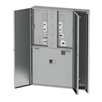
MEMSHIELD 4 INSTALLATION INSTRUCTIONS FOR
INCOMING AND OUTGOING METERING - 400A to 800A
Instruction leaflet LT1224 (01/19)
IMPORTANT NOTES
1. This product should be installed, commissioned and maintained by or under the supervision of a competent electrician in
accordance with current electrical engineering Codes of Practice, Requirements for the Electrical Installations (IET Wiring
Regulations BS7671), Construction (Design and Management) Regulations, HSG150 - Health and Safety in Construction, Statutory
requirements and any Specific instruction issued by the Company.
2. After completing the installation and testing of this product it is essential that this leaflet is drawn to the attention of the
person responsible for its future operation and maintenance, and is at all times available for ready reference.
3. These notes assume throughout that the product is disconnected from the supply. It is essential that this is done before any
work is carried out.
4. These Panelboards are only designed for use with Eaton MCCBs. Failure to comply will result in invalid warranty and
certification.
METER SETTINGS
Basic Meter Setup:- For detailed meter settings see Meter Operating Instructions.
Press: "E " for 3 seconds to toggle from Auto to Manual mode. (Stops screen scrolling).
IMPORTANT- Do NOT perform 'Left Hand CT Mounting Phase Correction' in Meter Operating Instructions.
The meter phases L1, L2 & L3 are setup for the CT to be mounted on both the RH and LH side of the board.
L3
L2
L1
Meter/CT Ratio Setup - The meter default CT setting is 160A. To
change the meter CT setting follow instructions below.
1. Press
+
keys together for 3 seconds to enter configuration menu.
2. To enter default password 1000 - Press
times to move on and to enter CT primary page 04.
3. Press
to select the digit to change and press
lower the CT value. Set to 250, 400, or 800 to match CT.
4. Press
to save settings and move on.
5. Press
+
keys together for 3 seconds to exit configuration menu.
POWER SUPPLY TAP OFF FITTING EM4PBVT
Fit the DIN rail before mounting the fuse block.
For Incoming Meter Pack always fit the fuse block on the LH side,
otherwise the fuse block can be fitted on either side of the pan.
Feed the cables through the grommet and position to suit the
breakout in the top busbar removable shield. Replace the shield
and ensure the grommet is captured in the breakout.
breakout
Fuse block
N/L3
L2
L1
N
L3
L2
L1
N
then press
.
or
to raise or
Removable shield
L3
L1 L2
N
L1
L2
L3
METER TYPES
EPBMETER1 – Modbus/Pulse.
EMC3PP2P1 – Multi function MID with
Modbus/Pulse.
Press
4
Note:
1. Ensure wire seal is fitted to MID Meter.
2. MID Meter will time out and lock, when
setting CT ratio, if meter setup instruction
are not followed.
INCOMING METER BOX ASSEMBLY - EM4PB250EXM AND METER
Incoming Meter Box can be fitted top or bottom.
Cable tidy Trunking
CT in
Pulse/Modbus
L1
Voltage
L2
I/P
L3
Power
L1
EM4PB250EXM
METER
Voltage
O/P
Power
Out
In
RJ45 CT
Connection
L3
L2
Advertisement

Related Manuals for Eaton MEMSHIELD 4


Summary of Contents for Eaton MEMSHIELD 4
- Page 1 3. These notes assume throughout that the product is disconnected from the supply. It is essential that this is done before any work is carried out. 4. These Panelboards are only designed for use with Eaton MCCBs. Failure to comply will result in invalid warranty and certification.
- Page 2 400A INCOMER METER KIT FITTING - Refer to main installation leaflet LTXXXX for additional fitting details (EM4PBK404 and EM4PBK404L) 400A LUGS INCOMER FITTING EM4PBK404LM 400A MCCB INCOMER FITTING EM4PBK404M To Meter 31Nm 31Nm L2 L3 N L1 L2 L3 N L1 31Nm 31Nm TOP ENTRY FITTING EM4PBK404M...
- Page 3 OUTGOING METER ASSEMBLY - OUTGOING METER CABLEWAYS CT KIT FITTING EM4PB68SXM, EPBN21240SXM, EPBCTMT160, EPBCTMT250 AND EPBCTMT400 EM4PB1214SXM, EM4PB1618SXM The CT can be fitted in the panelboard or cableway CORNER FILLER - EM4PB300CX for both group or compartmentailsed except in the following instances: Box fixing, ensure scratch washers - NZM3 CT must be fitted in the Cableway for...
- Page 4 Intellectual Property Rights control. Particular care should therefore be taken to follow the instructions Eaton wishes to make it clear that it owns intellectual property rights in the given here and to ensure their continued availability in conjunction with the product which it manufactures (whether or not listed in this leaflet) and that it use of the product.
Need help?
Do you have a question about the MEMSHIELD 4 and is the answer not in the manual?
Questions and answers