
Related Manuals for Eaton COOPER POWER E

Summary of Contents for Eaton COOPER POWER E
- Page 1 COOPER POWER Reclosers SERIES Effective May 2017 MN280051EN Supersedes April 2014 (S280-10-8) Types E, 4E, V4E, H, 4H, V4H, L, and V4L single-phase recloser installation and operation instructions...
- Page 2 CONTENTS OF THIS DOCUMENT SHALL NOT BECOME PART OF OR MODIFY ANY CONTRACT BETWEEN THE PARTIES. In no event will Eaton be responsible to the purchaser or user in contract, in tort (including negligence), strict liability or other-wise for any special, indirect, incidental or consequential damage or loss whatsoever, including but not limited to...
-
Page 3: Table Of Contents
Contents DISCLAIMER OF WARRANTIES AND LIMITATION OF LIABILITY . . . . . . . . . . . . . . . . . . . . . . . . . . . . . . . . . . . . I SAFETY FOR LIFE . -
Page 4: Safety For Life
FOR LIFE FOR LIFE Eaton’s Cooper Power series products meet or exceed all applicable industry standards relating to product safety. We actively promote safe practices in the use and maintenance of our products through our service literature, instructional training programs, and the continuous efforts of all Eaton employees involved in product design, manufacture, marketing, and service. -
Page 5: Product Information
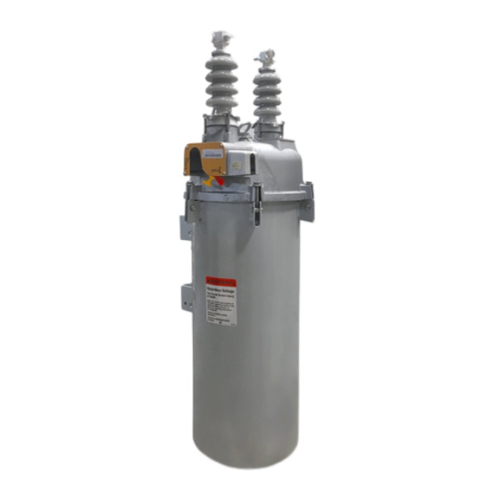
Reclosers in the E, H, and L groups (see cover photo) instructions, operation information, and testing procedures are self-contained, hydraulically controlled devices that for Cooper Power series single-phase reclosers from Eaton. sense and interrupt fault currents on single-phase lines Before installing and operating this recloser, carefully read of an electrical power distribution system. -
Page 6: Series-Trip Solenoid
Types E, 4E, V4E, H, 4H, V4H, L, and V4L single-phase recloser installation and operation instructions Series-trip solenoid Fault-current sensing is provided by a series-connected solenoid coil that carries line current. When a fault occurs, Sleet hood tripping is initiated by the solenoid plunger. The plunger, normally held at rest by the closing springs, is drawn into the coil by the magnetic force generated by the fault current. -
Page 7: Data Plates
Types E, 4E, V4E, H, 4H, V4H, L, and V4L single-phase recloser installation and operation instructions Data plates The recloser data plates, located on the sleet hood (see Figure 2), provide ratings information including: product type and serial number, nominal operating voltage, maximum-interrupting current, trip coil rating, operating sequence, and number of operations to lockout. -
Page 8: Ratings And Specifications
Types E, 4E, V4E, H, 4H, V4H, L, and V4L single-phase recloser installation and operation instructions Ratings and specifications Table 1 . Ratings and specifications 60 Hz Insulation level Rated system Rated system withstand rating nominal Rated system withstand voltage Continuous Recloser type voltage (kV) - Page 9 Types E, 4E, V4E, H, 4H, V4H, L, and V4L single-phase recloser installation and operation instructions Table 3 . Interrupting ratings Trip-coil Minimum- Recloser continuous trip current Interrupting current Trip-coil Minimum- type current (amps) (amps) (rms symmetrical amps) Recloser continuous trip current Interrupting current @4.8...
-
Page 10: Dimensions And Weights
Types E, 4E, V4E, H, 4H, V4H, L, and V4L single-phase recloser installation and operation instructions Dimensions and weights Table 5 . Recloser dimensions Recloser type Figure 6 provides dimensional information for the Type H 4E, V4E 4H, V4H recloser. Figure 7 provides dimensions for the E, H, and L Description mm (in) mm (in) -
Page 11: Installation Procedure
Types E, 4E, V4E, H, 4H, V4H, L, and V4L single-phase recloser installation and operation instructions Installation procedure Continue opening and closing the recloser manually until lock-out is achieved. This can be determined by listening for unlatching of the lock-out mechanism WARNING and also by noting that the recloser mechanism will not latch when the operating handle is moved... -
Page 12: Operation
Types E, 4E, V4E, H, 4H, V4H, L, and V4L single-phase recloser installation and operation instructions BYPASS SWITCH RECLOSER SOURCE SOURCE LOAD LOAD DISCONNECT DISCONNECT SWITCH SWITCH SURGE SURGE ARRESTER ARRESTER MULTIGROUNDED NEUTRAL Figure 8 . Connection diagram with switches to facilitate maintenance and complete surge protection Operation Manual operation WARNING... -
Page 13: Maintenance Information
. G107 .3 Factory-authorized service centers All Eaton’s Cooper Power series reclosers require routine Factory-authorized service centers are located throughout inspection and maintenance to ensure proper operation. If the continental United States to provide maintenance,... - Page 14 Types E, 4E, V4E, H, 4H, V4H, L, and V4L single-phase recloser installation and operation instructions This page is intentionally left blank. OPERATION INSTRUCTIONS MN280051EN May 2017...
- Page 15 Types E, 4E, V4E, H, 4H, V4H, L, and V4L single-phase recloser installation and operation instructions This page is intentionally left blank. OPERATION INSTRUCTIONS MN280051EN May 2017...
- Page 16 Waukesha, WI 53188 United States Eaton.com/cooperpowerseries © 2017 Eaton All Rights Reserved Printed in USA Eaton is a registered trademark. For Eaton's Cooper Power series product Publication No. MN280051EN information May 2017 call 1-877-277-4636 or visit: All trademarks are property www.eaton.com/cooperpowerseries.
Need help?
Do you have a question about the COOPER POWER E and is the answer not in the manual?
Questions and answers