Table of Contents
Advertisement
Technical Data TD534-0501002U
Instructions for the Installation,
Effective January 2013
Contents
Description
Overview . . . . . . . . . . . . . . . . . . . . . . . . . . . . . . . . . . . . . . . .
Introduction . . . . . . . . . . . . . . . . . . . . . . . . . . . . . . . . . . . .
Order instruction . . . . . . . . . . . . . . . . . . . . . . . . . . . . . . . .
Standard conformance . . . . . . . . . . . . . . . . . . . . . . . . . . .
Ambient conditions . . . . . . . . . . . . . . . . . . . . . . . . . . . . . .
Specification and technical data . . . . . . . . . . . . . . . . . . . . . .
Product structure and working principles . . . . . . . . . . . . . . .
Main device structure . . . . . . . . . . . . . . . . . . . . . . . . . . . .
Operation principles . . . . . . . . . . . . . . . . . . . . . . . . . . . . .
Fuse interlocking . . . . . . . . . . . . . . . . . . . . . . . . . . . . . . .
Cradle interlocking . . . . . . . . . . . . . . . . . . . . . . . . . . . . . .
Dimensions . . . . . . . . . . . . . . . . . . . . . . . . . . . . . . . . . . .
Schematic wiring diagram . . . . . . . . . . . . . . . . . . . . . . . .
Mounting, commissioning and operating . . . . . . . . . . . . . . .
Receiving, handling and storage . . . . . . . . . . . . . . . . . . . .
Commissioning and operating . . . . . . . . . . . . . . . . . . . . .
Maintenance . . . . . . . . . . . . . . . . . . . . . . . . . . . . . . . . . . . . .
Inspection of vacuum interrupter . . . . . . . . . . . . . . . . . . .
Inspection of contact's wear-out . . . . . . . . . . . . . . . . . . .
Inspection of mechanisms . . . . . . . . . . . . . . . . . . . . . . . .
Usage of fuses . . . . . . . . . . . . . . . . . . . . . . . . . . . . . . . . .
Replacement of fuses . . . . . . . . . . . . . . . . . . . . . . . . . . .
Supplied documents and accessories . . . . . . . . . . . . . . . . .
Ordering information . . . . . . . . . . . . . . . . . . . . . . . . . . . . . .
Safety precautions . . . . . . . . . . . . . . . . . . . . . . . . . . . . . . . .
Page
1
1
1
1
1
2
3
3
3
3
3
4
5
7
7
7
8
8
8
8
8
8
9
9
9
Advertisement
Table of Contents

Related Manuals for Eaton W-SLC-7.2


Summary of Contents for Eaton W-SLC-7.2
-
Page 1: Table Of Contents
Technical Data TD534-0501002U Effective January 2013 Instructions for the Installation, Operation and Maintenance of W-SLC-7.2 Contents Description Page Overview ........ -
Page 2: Operation And Maintenance
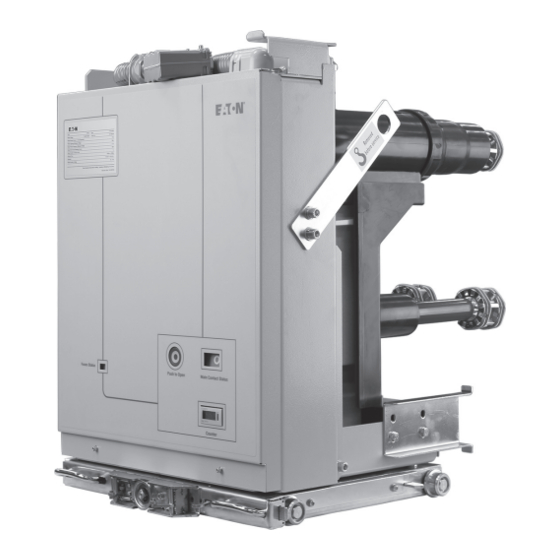
W-SLC is a contactor fuse combination withdrawable truck for use in indoor switchgear. It is rated at a continuous current rating of 400A (with conductors) and 200A (with 355A fuses) and used up to 7.2kV 50Hz AC power systems. Incorporating Eaton’s fixed type SL series of medium voltage vacuum contactors. -
Page 3: Specification And Technical Data
Instructions for the Installation, Technical Data TD534-0501002U Operation and Maintenance Effective January 2013 of W-SLC-7.2 Specifications and technical data Key specifications and technical data are shown in below table: Withdrawable Withdrawable Contactor with Contactor with Key technical data Units Conductors... -
Page 4: Product Structure And Working Principles
10. Counter Operation principle Cradle interlocking The W-SLC utilizes Eaton vacuum interrupters that exhibit both a The cradle of the unit is interlocked such that the contactor cannot long electrical life and a high interruption capability. be closed if the truck is not racked into the ‘Service’ position. The... -
Page 5: Dimensions
Instructions for the Installation, Technical Data TD534-0501002U Operation and Maintenance Effective January 2013 of W-SLC-7.2 Dimensions Please refer to Figure 2 for W-SLC dimensions. Figure 2 Note: dimension unit (mm) EATON CORPORATION www.eaton.com... -
Page 6: Schematic Wiring Diagram
Instructions for the Installation, Operation and Maintenance Effective January 2013 of W-SLC-7.2 Schematic wiring diagram The wiring diagrams Fig. 3 and Fig. 4 show the unit in the withdrawn position and the contactor open. The diagram is for reference only, please refer to the wiring diagram with the product for most accurate information as customer specific wiring may have been included for a specific purpose. - Page 7 Instructions for the Installation, Technical Data TD534-0501002U Operation and Maintenance Effective January 2013 of W-SLC-7.2 Figure 4 EATON CORPORATION www.eaton.com...
-
Page 8: Mounting, Commissioning And Operating
Receiving, handling and storage any loose or damaged parts. Please check whether the unit’s nameplate is in accordance with switchgear. If not, contact Eaton The W-SLC has completed full factory tests and inspection before immediately. Upon completion, insert the unit into the switchgear being packed. -
Page 9: Maintenance
Instructions for the Installation, Technical Data TD534-0501002U Operation and Maintenance Effective January 2013 of W-SLC-7.2 4. Troubleshooting: Phenomenon Causes Not able to close 1. The contactor is already in closed status 2. The cradle is not fully into the fully connected or test positions 3. -
Page 10: Supplied Documents And Accessories
Effective January 2013 of W-SLC-7.2 12. Rack into the panel once again. Use the cradle racking handle to rack the W-SLC-7.2 to ‘Service’ position, to be ready for operation. Notice: 1. In order to prevent unexpected accidents, works such as... - Page 11 Eaton’s electrical business is a global leader with expertise in power distribution and circuit protection; backup power protection; control and automation; lighting and security; structural solutions and wiring devices; solutions for harsh and hazardous environments; and engineering services. Eaton is positioned through its global solutions to answer today’s most critical...
Need help?
Do you have a question about the W-SLC-7.2 and is the answer not in the manual?
Questions and answers