Table of Contents
Advertisement
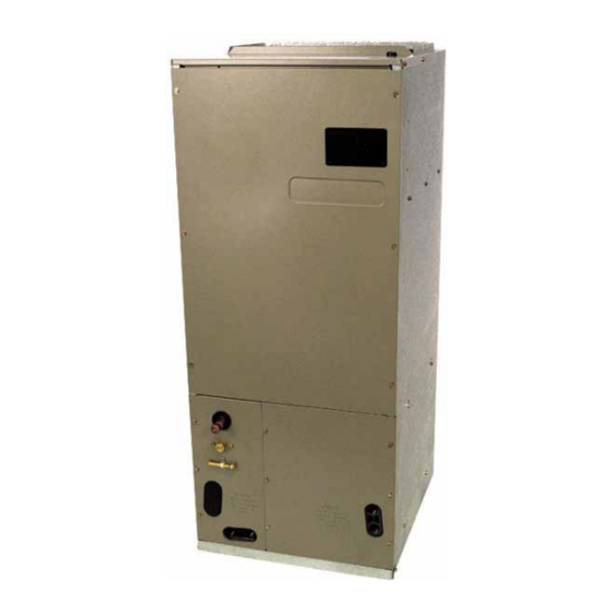
ASPF
AIR HANDLERS
INSTALLATION & OPERATING INSTRUCTIONS
CONTENTS
Important Safety Instructions ............................................. 2
Shipping Inspection ........................................................... 3
Codes & Regulations ........................................................ 3
Replacement Parts ............................................................ 3
Pre-Installation Instructions ............................................... 3
Location ............................................................................. 3
Ductwork ........................................................................... 3
Return Ductwork .............................................................. 4
Return Air Filters .............................................................. 4
Electric Heat ...................................................................... 4
HKR Installation ................................................................. 4
Electrical Supply Wire and MOP ....................................... 4
Building Electrical Service Inspection .............................. 5
Wire Sizing ...................................................................... 5
Maximum Overcurrent Protection (MOP) ........................ 5
Electrical Connections - Supply Voltage ......................... 5
Air Handler Only (Non-Heat Kit Models) ..................... 5
Air Handler With Non-Circuit Breaker Heat Kits .......... 5
Containing a Circuit Breaker ................................... 5
Low Voltage Connections ........................................... 6
Refrigerant Lines ............................................................... 6
Tubing Preparation .......................................................... 6
Post Brazing .................................................................... 6
Piping Size ...................................................................... 6
Special Instructions ......................................................... 6
Downflow Conversion ....................................................... 7
Horizontal Conversion ....................................................... 7
Condensate Removal ........................................................ 8
Achieve 2% Low Leakage Rate ........................................ 9
ASPF Motor ....................................................................... 9
CFM Delivery ................................................................... 9
Start-Up Procedure ........................................................... 9
Regular Maintenance ........................................................ 9
ASPF Thermostat Connections ....................................... 10
of 10kW and Below ................................................... 10
Observe all safety warnings. During installation or repair, caution is to be observed.
It is your responsibility to install the product safely and to educate the customer on its safe use.
RECOGNIZE THIS SYMBOL AS A SAFETY PRECAUTION.
ATTENTION INSTALLING PERSONNEL
Prior to installation, thoroughly familiarize yourself with this Installation Manual.
© 2007 - 2012 Goodman Manufacturing Company, L.P.
5151 San Felipe, Suite 500, Houston, TX 77056
www.goodmanmfg.com - or - www.amana-hac.com
P/N: IO-431A
Date: November 2012
Cooling Unit w/Optional Heat Kits
of 15kW and Above
and Room Thermostat w/Two Stages of Heat ........... 11
of 10kW and Below ................................................... 11
of 15kW and Above ................................................... 12
ASPF Wiring Diagram ..................................................... 13
Advertisement
Table of Contents

Related Manuals for Goodman ASPF Series


Summary of Contents for Goodman ASPF Series
-
Page 1: Table Of Contents
ASPF © 2007 - 2012 Goodman Manufacturing Company, L.P. 5151 San Felipe, Suite 500, Houston, TX 77056 AIR HANDLERS www.goodmanmfg.com - or - www.amana-hac.com INSTALLATION & OPERATING INSTRUCTIONS P/N: IO-431A Date: November 2012 Cooling Unit w/Optional Heat Kits CONTENTS of 15kW and Above Important Safety Instructions .......... -
Page 2: Important Safety Instructions
Goodman brand products, visit www.goodmanmfg.com and these requirements. ® for Amana brand products, visit www.amana-hac.com. is a registered trademark of Maytag Corporation or its related companies and is used under license to Goodman Company, L.P., Houston, TX. All rights reserved. -
Page 3: Shipping Inspection
® IMPORTANT: To register your Goodman brand unit, go to CONSUMER AFFAIRS www.goodmanmfg.com and click on “Warranty Registration”. GOODMAN MANUFACTURING COMPANY, L.P. Complete registration as prompted. 7401 SECURITY WAY HOUSTON, TEXAS 77040 ® To register your Amana brand unit, go to www.amana- hac.com and click “Warranty Registraion”. -
Page 4: Return Ductwork
Return Ductwork HEAT KIT NOMINAL kW DO NOT TERMINATE THE RETURN DUCTWORK IN AN AREA THAT CAN INTRODUCE TOXIC, OR OBJECTION- ABLE FUMES/ODORS INTO THE DUCTWORK. The return ductwork is to be introduced into the air handler bottom (upflow 1000 configuration). -
Page 5: Building Electrical Service Inspection
Maximum Allowable Length in Feet to Limit Voltage Drop to 2%* HIGH VOLTAGE! Disconnect ALL power before servicing. Minimum Circuit Ampacity (MCA) Wire Size Multiple power sources may be present. (AWG) Failure to do so may cause property damage, personal injury or death. HIGH VOLTAGE! To avoid property damage, personal injury or death due to electrical shock, this unit MUST have an... -
Page 6: Low Voltage Connections
However, in mix-matched applications, a flowrator piston 10. Replace suction line grommet and insulation. ® change may be required. See the Goodman piston kit chart or consult your local distributor for details regarding mix- SUCTION LINE WITH SPIN CLOSURE matched piston sizing. -
Page 7: Downflow Conversion
Downflow Conversion 7. Install the zee coil supports and the wrapper stiffeners. Conversion to downflow MUST be performed in an area that 8. Install the tie bracket. allows access to all sides prior to placing the air handler in its 9. -
Page 8: Condensate Removal
. the open Tee. Goodman® does not prohibit this type of drain 7. Install the plastic plug removed in step 5 to the right but we also do not recommend it due to the resulting air leak- side lower access panel and the oval shaped rubber age. -
Page 9: Achieve 2% Low Leakage Rate
Use of a condensate removal pump is permitted when nec- • Return and supply ducts are sealed. essary. This condensate pump should have provisions for • Unit is elevated when installed in a garage or where shutting off the control voltage should a blocked drain occur. flammable vapors may be present. -
Page 10: Aspf Thermostat Connections
LOW VOLTAGE TERMINAL BOARD. or two-stage electric heating. All these configurations can be applied with convenient connections to outdoor thermo- An equivalent thermostat can be used in place of the Goodman thermostat part number. stat applications. The following sections will be detailed: •... -
Page 11: And Room Thermostat W/Two Stages Of Heat
HIGH VOLTAGE! DISCONNECT ALL POWER BEFORE SERVICING. WARNING MULTIPLE POWER SOURCES MAY BE PRESENT. FAILURE TO DO SO MAY CAUSE PROPERTY DAMAGE, PERSONAL INJURY OR DEATH. #18 GA. 5 WIRES WITH COOLING 4 WIRES WITHOUT CONDENSING UNIT 24V CONNECTION COOLING UNIT WITH OPTIONAL HEAT KITS OF 15 kW AND ABOVE AND ROOM THERMOSTAT WITH TWO STAGES OF HEAT #18 GA. -
Page 12: Heat Pump Unit W/Optional Heat Kits Of 15Kw And Above
HIGH VOLTAGE! DISCONNECT ALL POWER BEFORE SERVICING. WARNING MULTIPLE POWER SOURCES MAY BE PRESENT. FAILURE TO DO SO MAY CAUSE PROPERTY DAMAGE, PERSONAL INJURY OR DEATH. #18 GA. 7 WIRE HEAT PUMP UNIT WITH OPTIONAL HEAT KITS OF 15 kW AND ABOVE NOTES: NOMENCLATURE: COLOR CODES... -
Page 13: Aspf Wiring Diagram
HIGH VOLTAGE! DISCONNECT ALL POWER BEFORE SERVICING. WARNING MULTIPLE POWER SOURCES MAY BE PRESENT. FAILURE TO DO SO MAY CAUSE PROPERTY DAMAGE, PERSONAL INJURY OR DEATH. ASPF Wiring Diagram HTR1 HTR1 HTR1 HTR 1 HTR2 HTR2 HTR2 HTR3 HTR3 HTR4 ONE (1) ELEMENT ROWS TWO (2) ELEMENT ROWS THREE (3) ELEMENT ROWS... - Page 14 THIS PAGE LEFT INTENTIONALLY BLANK...
- Page 15 SPLIT SYSTEMS AIR CONDITIONING AND HEAT PUMP HOMEOWNER’S ROUTINE MAINTENANCE RECOMMENDATIONS We strongly recommend a bi-annual maintenance checkup be performed before the heating and cooling seasons begin by a qualified servicer. Clean Outside Coil (Qualified Servicer Only) Replace or Clean Filter IMPORTANT NOTE: Never operate unit without a filter in- stalled as dust and lint will build up on internal parts resulting in loss of efficiency, equipment damage and possible fire.
- Page 16 NOTE: SPECIFICATIONS AND PERFORMANCE DATA LISTED HEREIN ARE SUBJECT TO CHANGE WITHOUT NOTICE. © 2007 - 2012 Goodman Manufacturing Company, L.P. 5151 San Felipe, Suite 500, Houston, TX 77056 www.goodmanmfg.com - or - www.amana-hac.com...
Need help?
Do you have a question about the ASPF Series and is the answer not in the manual?
Questions and answers