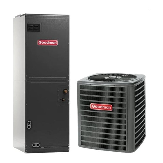
Goodman AVPTC 14 Series Installation & Operating Instructions Manual

Goodman AVPTC 14 Series Installation & Operating Instructions Manual

Advertisement

AVPTC**14** AIR HANDLERS
Installation & Operating
Instructions

Table of Contents

1
Important Safety Instructions ................................... 2
2
Shipping Inspection .................................................. 3
3
Codes & Regulations ................................................ 3
4
Replacement Parts .................................................... 3
5
Pre-Installation Considerations ............................... 3
6
Installation Location .................................................. 3
7
Refrigerant Lines ....................................................... 6
8
Condensate Drain Lines ........................................... 9
9
Ductwork ................................................................... 10
10 Return Air Filters ...................................................... 10
Low Leakage Rate .................................................... 10
12 Electric Heat .............................................................. 10
13 Electrical and Control Wiring .................................. 12
14 AVPTC Motor Ortientation ....................................... 13
15 Cool Cloud HVAC Phone Application ..................... 14
Outdoor Units ........................................................... 14
Outdoor Units ........................................................... 15
18 Dehumidification ...................................................... 16
19 Auxiliary Alarm Switch ............................................. 17
20 Start-up Procedure ................................................... 17
21 Accessories .............................................................. 17
22 Dehumidification Control Options .......................... 18
23 Ramping Profiles ...................................................... 19
24 Electric Air Cleaning ................................................ 20
25 Start-Up Procedure................................................... 20
26 Regular Maintenance ............................................... 20
27 Air Handler Troubleshooting Matrix ....................... 21
28 Air Handler Display .................................................. 23
29 Airflow Label ............................................................. 26
30 Wiring Diagram ......................................................... 27
31 Start-Up Checklist .................................................... 30
ATTENTION INSTALLING PERSONNEL
Prior to installation, thoroughly familiarize yourself with this Installation
Manual. Observe all safety warnings. During installation or repair,
caution is to be observed. It is your responsibility to install the product
safely and to educate the customer on its safe use.
RECOGNIZE THIS SYMBOL
AS A SAFETY PRECAUTION.
Do not bypass safety devices.
is a registered trademark of Maytag Corporation or its related companies and is used under license. All rights reserved.
WARNING
© 2018-2021, 2023
Daikin Comfort Technologies Manufacturing, L.P.
19001 Kermier Rd., Waller, TX 77484
www.goodmanmfg.com - or - www.amana-hac.com
P/N: IOA-4030H
Only personnel that have been trained to install, adjust,
service, maintenance or repair (hereinafter, "service")
the equipment specified this manual should service the
equipment.
This equipment is not intended for use by persons
(including children) with reduced physical, sensory or
mental capacities, or lack of experience and knowledge,
unless they have been given supervision or instruction
concerning use of the appliance by a person responsible
for their safety.
Children should be supervised to ensure that they do not
play with the equipment.
The manufacturer will not be responsible for any injury
or property damage arising from improper supervision,
service or service procedures. If you service this unit, you
assume responsibility for any injury or property damage
which may result. In addition, in jurisdictions that require
one or more licenses to service the equipment specified in
this manual, only licensed personnel should service the
equipment. Improper supervision, installation, adjustment,
servicing, maintenance or repair of the equipment specified
in this manual, or attempting to install, adjust, service
or repair the equipment specified in this manual without
proper supervision or training may result in product
damage, property damage, personal injury or death.
This device, which was assembled by Daikin Comfort
Technologies Manufacturing, L.P., contains a component
that is classified as an intentional radiator. This intentional
radiator has been certified by the FCC: FCC ID QOQBGM111.
And this international radiator has an Industry Canada ID: IC
5123A-BGM111.
This device complies with Part 15 of the FCC's Rules. Operation
of this device is subject to two conditions:
(1) This device may not cause harmful interference; and
(2) This device must accept any interference received, including
interference that may cause undesirable operation.
And this device meets the applicable Industry Canada technical
specifications.
The manufacturer of the intentional radiator (model no. BGM111)
is Silicon Laboratories Finland Oy, which can be contacted by
calling 617-951-0200. (www.silabs.com)
The FCC responsible party is Daikin Comfort Technologies
Manufacturing, L.P., and may be contacted by calling (713)-
816-2500, or at 19001 Kermier Rd., Waller TX 77484. (www.
GoodmanMFG.com)
This equipment complies with FCC radiation exposure limits. To
ensure compliance, human proximity to the antenna shall not be
less the 20cm during normal operations.
Date: April 2023
WARNING

Advertisement

Table of Contents
loading
Need help?

Need help?

Do you have a question about the AVPTC 14 Series and is the answer not in the manual?

Questions and answers

GARY EUGENE VAUGHAN
March 17, 2025

what ton unit will a Goodman model AVPTC313714AA furnace support? 3.0 or 3.5

1 comments:
Mr. Anderson
May 14, 2025

The Goodman AVPTC 14 Series model AVPTC313714AA furnace will support a 3.0-ton unit.

This answer is automatically generated

Subscribe to Our Youtube Channel

Summary of Contents for Goodman AVPTC 14 Series

  • Page 1: Table Of Contents

    AVPTC**14** AIR HANDLERS © 2018-2021, 2023 Daikin Comfort Technologies Manufacturing, L.P. Installation & Operating 19001 Kermier Rd., Waller, TX 77484 www.goodmanmfg.com - or - www.amana-hac.com Instructions P/N: IOA-4030H Date: April 2023 Table of Contents WARNING Important Safety Instructions ........2 Shipping Inspection ..........
  • Page 2: Important Safety Instructions

    1 Important Safety Instructions The following symbols and labels are used throughout this manual to indicate immediate or potential safety hazards. It is the owner’s and installer’s responsibility to read and comply with all safety information and instructions accompanying these symbols. Failure to heed safety information increases the risk of personal injury, property damage, and/or product damage.
  • Page 3: Codes & Regulations

    correct prior to installation. The distributor or manufacturer supplies needed to complete the installation. Some will not accept claims from dealers for transportation damage items may need to be purchased locally. Make sure or installation of incorrectly shipped units. everything needed to install the product is on hand before starting.
  • Page 4 This product line may be installed in one of the upflow, may now be removed. From Figure 1, drain port labeled downflow, horizontal left or horizontal right orientations as (A) is the primary drain for this application and condensate shown in Figures 2, 3, 4 and 5. The unit may be installed drain line must be attached to this drain port.
  • Page 5 6.2 Horizontal Left Installation (Figure 4) CMK0008 CMK0009 CMK0010 CMK0012 CMK0013 CMK0014 Condensa te Condensa te Condensa te Condensa te Condensa te Condensa te No field modifications are permissible for this application. Ki t Ki t Ki t Install unit as shown in Figure 4. AVPTC25B14 AVPTC29B14 AVPTC31C14 AVPTC49D14 AVPTC33C14 AVPTC49C14 Drain port labeled (B) in Figure 1 is the primary drain AVPTC37B14 AVPTC37C14 AVPTC61D14 AVPTC39C14...
  • Page 6: Refrigerant Lines

    7.2 Tubing Preparation All cut ends are to be round, burr free, and clean. Failure to follow this practice increases the chances for refrigerant leaks. The suction line is spun closed and requires tubing cutters to remove the closed end. NOTE: To prevent possible damage to the tubing joints, do not handle coil assembly with manifold or flowrator tubes.
  • Page 7 Upper Tie Plate Control Deck Blower Access Panel Downflow Bracket Coil Tubing Access Center Panel Panel Support Filter Bracket Filter Access Panel Knockout INTERNAL PART TERMINOLOGY Figure 6 EXTERNAL PART TERMINOLOGY Figure 7 IMPORTANT NOTE: Ensure coil slides on the rails along the groove provided on the drain pan side walls.
  • Page 8 4. Complete airflow tables and charging information are in Service Manual RS6200006. CAUTION 5. The outdoor temperature must be 60°F or higher. Applying too much heat to any tube can melt the tube. Torch heat required to braze tubes of various sizes must be 6.
  • Page 9: Condensate Drain Lines

    NOTE: In situations where the TXV must be removed and SATURATED LIQUID PRESSURE replaced or re-installed into the system, the TXV should be TEMPERATURE CHART hand tightened first and then apply a half turn to fully set the SATURATED LIQUID TXV.
  • Page 10: Ductwork

    9 Ductwork NOTE: Water coming from secondary line means the coil primary drain is plugged and needs immediate attention. This air handler is designed for a complete supply and return ductwork system. CAUTION To ensure correct system performance, the ductwork is to be sized to accommodate 350-450 CFM per ton of cooling If secondary drain is not installed, the secondary access with the static pressure not to exceed 0.5”...
  • Page 11 The heating mode temperature rise is dependent upon the 3412 = Btu per kW system airflow, the supply voltage, and the heat kit size = .96 (230 Supply Volts) (kW) selected. Use data provided in Tables 3, 4 and 5 to = .92 (220 Supply Volts) determine the temperature rise (°F).
  • Page 12: Electrical And Control Wiring

    1. Stage Up Percent (7 segment menu SUP): This is a unit or the capacity demand percentage for an inverter / value that determines how far past the target runtime modulating unit for the next cycle. NOTE: Actual run times the system should continue running the heat pump be- may change depending on variations of load throughout the fore transitioning to the furnace.
  • Page 13: Avptc Motor Ortientation

    13.4 Electrical Connections – Supply Voltage CAUTION IMPORTANT NOTE: USE COPPER CONDUCTORS ONLY. FIRE HAZARD! To avoid the risk of property damage, personal injury or fire, Knockouts are provided on the air handler top panel use only copper conductors. and sides of the cabinet to allow for the entry of the supply voltage conductors, as shown in Figure 13.
  • Page 14: Cool Cloud Hvac Phone Application

    FRONT VIEW SIDE VIEW FEMALE CONNECTIONS AVPTC MOTOR ORIENTATION Figure 13 15 Cool Cloud HVAC Phone Application NOTE: This equipment has been tested and found to comply with the limits for a Class B digital device, pursuant to part Figure 14 15 of the FCC Rules.
  • Page 15: Quick Start Guide For Non-Communicating Outdoor Units

    NOTE: When installing the air handler with a non-com- municating heat pump, wire directly to the “O” terminal on the non-communicating heat pump. See the following figures. COMMUNICATING TWO-STAGE AIR CONDITIONER OR HEAT PUMP Figure 15 NON-COMMUNICATING SINGLE STAGE A/C 3.
  • Page 16: Dehumidification

    NOTE: The system will not provide airflows above the max Airflow Value. ModelM AX CFM AVPTC25B14 AVPTC29B14 1200 AVPTC35B14 AVPTC37B14 AVPTC33C14 1300 AVPTC31C14 AVPTC37C14 1600 AVPTC39C14 AVPTC37D14 1800 AVPTC49C14 AVPTC49D14 1900 AVPTC59C14 NON-COMMUNICATING TWO STAGE HEAT PUMP Figure 19 AVPTC59D14 2100 AVPTC61D14 2.
  • Page 17: Auxiliary Alarm Switch

    19 Auxiliary Alarm Switch The control is equipped with a 24VAC Aux Alarm to be used for a condensate switch install (designated by CONDENSATE IN/OUT on the control). By default, the connected AUX switch is normally closed and opens when the water level in the evaporator coil base pan reaches an undesirable level.
  • Page 18: Dehumidification Control Options

    22 Dehumidification Control Options Key Mitigations: Full featured TS (dehum & overcool) Connect G and dehum wire correctly Dehumidistat Dehumidification Control Options Dry Environment Install any 24VAC Thermostat has a Dehum or thermostat on the Configurable terminal with market - Use Y, W, G Dehum option signals Install Dehumidistat in...
  • Page 19: Ramping Profiles

    21 Accessory Control (Humidifiers, 23 Ramping Profiles Dehumidifiers, Ventilators) The variable-speed circulator offers four different ramping profiles. These profiles may be used to enhance cooling If an external humidifier, dehumidifier or ventilator is performance and increase comfort level. Select the desired installed, it may require airflow from the HVAC system to ramping profile using the Cool Cloud phone application or function properly.
  • Page 20: Electric Air Cleaning

    24 Electric Air Cleaner Warning • Low voltage wiring is connected. The control is equipped with an Accessory Relay and a • Auxiliary drain is installed when necessary and pitched pair of ¼ inch accessory terminals which is normally open, to allow for drainage.
  • Page 21: Air Handler Troubleshooting Matrix

    27 Air Handler Troubleshooting Matrix Diagnostic / Symptoms of Abnormal Operation Status LED Fault Description Possible Causes Corrective Actions Codes Improper low voltage wiring between Locate and correct improper low voltage wiring the indoor and outdoor unit issue Communication error with No outdoor unit operations ...
  • Page 22 27 Air Handler Troubleshooting Matrix (continued) Diagnostic / Symptoms of Abnormal Status LED Fault Description Possible Causes Corrective Actions Operation Codes Circulator blower motor senses a loss of rotor Abnormal motor loading, Check filters, filter grills/registers, control sudden change in speed or No Air Handler operation duct system and air handler ...
  • Page 23: Air Handler Display

    28 Air Handler Display LED Display Menu Description View 6 most recent fault codes and Clear Fault Codes if desired  (furnace) Restart communications between the indoor and outdoor unit.  Control Firmware Revision Number  Control Shared Data Revision Number ...
  • Page 24 28 Air Handler Display (continued) LED Display Menu Description View 6 most recent fault codes and Clear Fault Codes if desired  (outdoor communicating units) Menu is enabled if the  menu is set to 6. Select the target time ...
  • Page 25 28 Air Handler Display (continued) LED Display Descrip�on of System Status  Idle Constant Fan  Compressor Cooling, Single-Stage (non-comm units)  Compressor Cooling, Low Stage (non-comm units)  Compressor Cooling, High Stage (non-comm units)  Compressor Cooling, Low Stage (comm units) ...
  • Page 26: Airflow Label

    29 Air Flow Label Menu Navigation and Selection Instructions Tonnage Menu (t o n) Using Phone Application over Bluetooth Network: 1) Connect to the air handler (instructions provided by phone during Tonnage Tonnage connection process). Airflow Airflow 2) Select desired settings menu Selection Selection 3) Select item that requires adjustment and make necessary selection...
  • Page 27: Wiring Diagram

    30 Wiring Diagrams HIGH VOLTAGE! ISCONNECT ALL POWER BEFORE SERVICING OR INSTALLING THIS UNIT ULTIPLE POWER SOURCES MAY BE PRESENT AILURE TO DO SO MAY CAUSE PROPERTY DAMAGE PERSONAL INJURY OR DEATH (SEE NOTE 4) 208/230 VAC GROUND LUG L2 L1 HEATER KIT (SEE NOTE 6) RD BK...
  • Page 28 3-Phase Heat Kit 30 Wiring Diagrams Wiring is subject to change. Always refer to the wiring diagram on the unit for the most up-to-date wiring.
  • Page 29 AIR HANDLER AIR HANDLER HOMEOWNER’S ROUTINE MAINTENANCE RECOMMENDATIONS We strongly recommend a bi-annual maintenance checkup be performed before the heating and cooling seasons begin by a qualified servicer. REPLACE OR CLEAN FILTER An alternate cleaning method is to use one of the products listed in TP-109* to clean the coils.
  • Page 30: Start-Up Checklist

    31 Start-up Checklist Air Handler / Coil Model Number Serial Number ELECTRICAL Line Voltage (Measure L1 and L2 Voltage) L1 - L2 Secondary Voltage (Measure Transformer Output Voltage) R - C Blower Amps Heat Strip 1 - Amps Heat Strip 2 - Amps BLOWER EXTERNAL STATIC PRESSURE Return Air Static Pressure IN.
  • Page 31 THIS PAGE IS LEFT INTENTIONALLY BLANK.
  • Page 32 CUSTOMER FEEDBACK We are very interested in all product comments. Please fill out the feedback form on one of the following links: Goodman Brand Products: (http://www.goodmanmfg.com/about/contact-us). ® Amana Brand Products: (http://www.amana-hac.com/about-us/contact-us). ® You can also scan the QR code on the right for the product brand you purchased to be directed to the feedback page.

This manual is also suitable for:

Avptc37c14Avptc39c14Avptc49c14Avptc33c14

Table of Contents

Save PDF