Table of Contents
Advertisement
Advertisement
Table of Contents
Troubleshooting

Related Manuals for Trane ReliaTel


Summary of Contents for Trane ReliaTel
- Page 1 Diagnostic Manual ReliaTel™ Microprocessor Controls RT-SVD03G-EN November 2010...
-
Page 2: Introduction
ReliaTel Introduction ReliaTel is not the name of a circuit board, but rather an overall communicating control system consisting of up to eight communicating modules. ReliaTel is the name given to the second generation microprocessor controls developed by Trane. -
Page 3: Table Of Contents
........... . 9 ReliaTel vs. Electromechanical ........9 ReliaTel –... - Page 4 ReliaTel Air Handling Module (RTAM) ....... 45 Green system LED ..........45 ReliaTel Dehumidification Module (RTDM) .
- Page 5 2-stage units ..........89 ReliaTel Hot Surface Ignition Control (12.5 - 50 Ton 1 Stage, 2 Stage, and Mod- ulating Gas Heat) .
- Page 6 ReliaTel Economizer Inputs ........106 Economizer Actuator Module W7340A1004 (used prior to 08/1/05) . . . 106 Service Tips .
- Page 7 ............135 3 – 25 Ton ReliaTel Units .
- Page 8 RTRM - ReliaTel Refrigeration Module - (standard) ....146 RTOM - ReliaTel Options Module - (standard) ....147 RTAM - ReliaTel Air Handler Module - (standard on VAV) .
-
Page 9: General Information
Each ReliaTel Module is a communicating control. ReliaTel Refrigeration Module (RTRM) Every ReliaTel unit uses an RTRM. The RTRM provides primary unit control for heating and cooling. In addition, it has built-in logic that controls heating and cooling staging, minimum run times, diagnostics, heat pump defrost control, short cycle timing and more. - Page 10 VariTrac™ 1 (Comfort Manager) • VariTrac™ 2 (Central Control Panel) LonTalk® Communication Interface Allows Building Management System (BMS) communication to a ReliaTel unit. There are 2 LCI versions, one for SCC control (constant volume units) and one for DAC control (VAV units). RT-SVD03G-EN...
-
Page 11: Module Flow Diagram
Module Flow Diagram Figure 1. TSC/THC Refrigeration Module (RTRM) Electric Heat/No Heat Unit Control, Select one TS/H Refrigeration Module 4 Zone Sensor Inputs (AIP) Zone Sensor 4 Outputs Mechanical LED or indications Non Heat Pump Config (BIP) 1 Compressor Config (BIP) Thermostat G Y1 Y2 W1 1 Stage Heat Config (BIP) - Page 12 Module Flow Diagram RTRM Figure 2. Refrigeration Module (RTRM) Gas Heating Unit Control, Select one YS/H Refrigeration Module 4 Zone Sensor Inputs (AIP) Gas Heat Zone Sensor Module 4 Outputs 1200 BPS Comm Mechanical (IGN) LED or indications Non Heat Pump Config (BIP) 1 Compressor Config (BIP) Thermostat G Y1 Y2 W1...
- Page 13 Module Flow Diagram RTRM Figure 3. Refrigeration Module (RTRM) Heat Pump Unit Control, Select one WS Refrigeration Module 4 Zone Sensor Inputs (AIP) Zone Sensor 4 Outputs Mechanical LED or indications No Electric Heat Configuration (BIP) (open when heaters installed) 1 Stage Electric Heat Config.
- Page 14 Module Flow Diagram RTOM Figure 4. Options Module (RTOM) Refrigeration Module Options Module Economizer Modbus Communication Actuator Module 24 VAC Voyager 3 Configuration Condenser Fan Cycling (27 .5 - 50 ton) Modulating Gas Heat Configuration Supply Air Tempering Config (BIP) Heat Pump Low Ambient Limit Config.
- Page 15 Module Flow Diagram Figure 5. Honeywell Economizer Module (ECA) Honeywell Economizer Module Power Exhaust Refrigeration relay Module ModBus Communication 24 VAC Status LED 24 VAC Enthalpy/Temperature Setpoint Pot. 0-50% Minimum Position Pot. Setpoint Adjustment (500-1500 ppm) MA Sensor Mixed Air Temp (AIP) 10K 25C Neg Coeff RH Sensor Return Air Relative Humidity (AIP)
- Page 16 Module Flow Diagram RTEM Figure 6. Economizer Module (RTEM) ReliaTel Economizer Module DCV Mode Power Exhaust Refrigeration relay Module ModBus Communication 24 VAC Status LED 24 VAC 24 VAC DCV Min Pos 0-40/50% Design Min Pos 0-10/50% Enthalpy/Temperature Setpoint Pot.
- Page 17 Module Flow Diagram LCI/TCI Figure 7. COMM 3/4 Module for ICS Communication/ LonTalk Communication Interface (LCI/TCI) Refrigeration Module Options COMM 3/4 Module/LCI Module Modbus Communication 24 VAC RTAM (VAV) Must be configured for COMM3 or COMM4 depending on input device. LCI is self-configured.
- Page 18 Module Flow Diagram RTAM Figure 8. Air Control Module (RTAM) Options TCI/LCI RTAM Module Module Refrigeration Static Pressure Setpoint Module Static Pressure Deadband VAV Box Relay Reset Remote Static Setpoint Pressure Setpoint Reset Duct Static Pressure Transducer Remote Static Amount Pressure Deadband Morning Remote Reset...
- Page 19 Module Flow Diagram RTVM Figure 9. ReliaTel Ventilation Module (RTVM) Options Module Ventilation Module Modbus Communication 24 VAC Statitrac Config Exhaust Damper Output Bldg. Pressure Transducer Calibration Output Bldg. Pressure Transducer Bldg. Pressure Setpoint Bldg. Pressure Setpoint Deadband RT-SVD03G-EN...
-
Page 20: Low Voltage Terminal Strip
Low Voltage Terminal Strip TEST terminals. By jumpering from TEST1 to TEST2, the service technician can test the unit or start it with or without any controls attached. See TEST MODE section for details. Compressor 1 disable. If the factory installed jumper from 1 to 2 is removed (Compressor 1 disable), compressor 1 will not run, even in the TEST MODE. -
Page 21: Typical Control Box Layout
Typical Control Box Layout Figure 12. Typical Control Box Layout (3-5 tons) Ignition Module (IGN) ReliaTel Refrigeration Module (RTRM) TCI (or LCI) Communication Fan Relay Compressor Module Contactor Crankcase Heater Thermostat OD Fan Inducer Capacitor transformer Zone sensor or (460/575 only) - Page 22 Typical Control Box Layout Figure 13. Typical Control Box Layout (T/YSC072-102E, T/YHC048-072E, & WSC060-090E) Ignition Module (IGN) ReliaTel Refrigeration Module (RTRM) TCI (COMM3/4) or LCI Interface Fan Relay Compressor Contactors Inducer Transformer (460/575 only) OD Fan Capacitor Zone Sensor or...
- Page 23 Typical Control Box Layout Figure 14. Typical Control Box Layout (T/YSC120E, T/YHC092-120E, & WSC120E) RT-SVD03G-EN...
- Page 24 Typical Control Box Layout Figure 15. Typical Control Box Layout (12½ - 25 tons) Ignition Module Fan Relay Compressor Contactors RTOM (Options Module) RTRM (Refrigeration Module) Zone Sensor or Thermostat Connections TCI (or LCI) Communication Module 24 VAC Control Transformer Low Voltage Terminal Block Test Terminals...
-
Page 25: Reliatel Refrigeration Module (Rtrm)
ReliaTel Refrigeration Module (RTRM) Figure 16. ReliaTel Refrigeration Module (RTRM) - Layout Common ModBus Config - Extended Heat Communication Common 24 VAC Receive LED Conventional Conventional (Yellow) Thermostat Thermostat Gas Heat W1 (YC, TC) O (WC) W1/O Communication 2 Stage Heat Config... -
Page 26: Rtrm Diagnostics
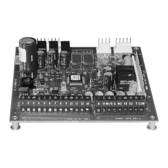
ReliaTel Refrigeration Module (RTRM) Figure 17. ReliaTel Refrigeration Module (RTRM) - Board Connections RTRM Diagnostics Note: For production, several versions of the RTRM are used depending on unit functions. There is one replacement module for all units. RTRM System LED Diagnostic Indicator On RTRM version 4.0 or higher, the green system LED on the RTRM module can provide a quick... - Page 27 ReliaTel Refrigeration Module (RTRM) Froststat Active Outdoor Air Temperature Sensor Failure Smoke Detector Active Entering Evaporator Temp. Failure (On Modulating Reheat Units) RTOM Comm. Failure RTDM Comm. Failure (On Modulating Reheat Units) RTVM Comm. Failure Space Pressure Sensor Failure Dehumidification Mis-Configuration Reheat Circuit Entering Evaporator Temperature Failure 27½...
- Page 28 ReliaTel Refrigeration Module (RTRM) Service Diagnostic What the readings mean Service- RTRM-J6-10. ON - Clogged filter switch has been closed for at least 2 minutes, indicating a clogged filter. This example illustrates what would be seen if the unit did not have a zone sensor with indicator LEDs, such as would be the case with an ICS system.
- Page 29 ReliaTel Refrigeration Module (RTRM) System Diagnostic What the readings mean System- RTRM-J6-9. ON – System is powered up. This output should be on whenever the green RTRM System LED is on. Incidentally, this LED may flicker as part of its normal function on older version boards.
- Page 30 ReliaTel Refrigeration Module (RTRM) Cool Diagnostic What the readings mean Cooling-RTRM-J6-8. ON – System is in the cooling mode and actively cooling. The unit could be economizing or have one or both compressors on. If the unit is a heat pump, the reversing valve is energized as well.
- Page 31 ReliaTel Refrigeration Module (RTRM) Heat Diagnostic What the readings mean Heating-RTRM-J6-7. ON – System is actively heating. OFF – System is not actively heating. PULSING – See below: Gas heat If any failure occurs such as loss of flame, limit switch trip, flame rollout etc, this indication is present.
- Page 32 ReliaTel Refrigeration Module (RTRM) Heat Fail - Cool Fail Diagnostic What the readings mean HEAT FAIL and COOL FAIL at the same time, RTRM-J6-7 & 8 pulsing voltage: 1. Coil temperature sensor is open or shorted. (Heat Pump) 2. Unit has failed to defrost properly. See Heat Pump section for further details.
-
Page 33: 27½ To 50 Ton Unit Additional Diagnostics (Vav Only)
ReliaTel Refrigeration Module (RTRM) 27.5-50 Ton VAV Diagnostic Unit is in OFF mode locally or through TCI/LCI Heat Pump- Compressors will not run 1. Unit is in the EMERGENCY HEAT mode. 2. If the Compressor Disable circuit or CC1, CC2 circuits create a lockout during heating mode, a COOL FAIL (pulsing) indication will occur, not a HEAT FAIL (pulsing) indication. -
Page 34: Default Operations
3. The MWU initiate setpoint is nciSetpoints.occupied heat - 1.5F . Default Operations The ReliaTel Refrigeration Module (RTRM) can accept input from any of the following: Mechanical Zone Sensor Module (ZSM) BAYSENS106-111A, AYSTAT106A-109A. Programmable Zone Sensor BAYSENS119*, AYSTAT666*Conventional thermostat BAYSTAT036- 038A (or similar). - Page 35 ReliaTel Refrigeration Module (RTRM) Note: Version 1.1 and 1.3 RTRM do not provide Heat, Cool, Service, Cool Fail, Heat Fail indications for Programmable ZSM. Later versions (with a higher number) do. COMM3/4 and COMM5 Communication Interface Module use MODBUS communication directly with the RTRM.
-
Page 36: Reliatel Option Module (Rtom)
12½ to 50 Ton The RTOM is installed in the control panel. Figure 18. ReliaTel Option Module (RTOM) Layout 1 2 3 4 5 6 7 Modulating Gas... -
Page 37: Rtom Inputs
J3-1 to J3-2 – Allows supply air tempering when using a mechanical ZSM. Removed = supply air tempering enabled, installed = disabled. Supply air tempering can also be enabled or disabled by using the BAYSENS019*/AYSTAT666* or a Trane ICS system. J3-3 is modulating gas heat config. input J3-4 is used with 27.5 - 50 ton units to configure condenser fan control type. -
Page 38: Setpoint Potentiometers
ReliaTel Option Module (RTOM) Smoke detector contacts are open during normal operation. When closed, the unit shuts down immediately. When the contacts are re-opened, the unit will automatically restart. Note: Ventilation override option will override smoke detector input through the RTOM. - Page 39 ReliaTel Option Module (RTOM) Table 7. RTOM Discharge Air Heat Setpoint Voltage (Vdc) Setpoint (ºF) Voltage (Vdc) Setpoint (ºF) Voltage (Vdc) Setpoint (ºF) 0.00 1.46 2.23 0.09 1.48 2.24 0.13 1.51 2.25 0.16 1.53 2.26 0.20 1.56 2.28 0.24 1.58 2.29...
- Page 40 ReliaTel Option Module (RTOM) Table 8. RTOM Supply Air Reheat Setpoint Voltage (Vdc) Setpoint (ºF) Voltage (Vdc) Setpoint (ºF) 0.002 1.683 0.169 65.5 1.766 73.5 0.317 1.822 0.395 66.5 1.887 74.5 0.552 1.940 0.672 67.5 1.998 75.5 0.785 2.064 0.915 68.5...
-
Page 41: Reliatel Ventilation Module (Rtvm)
ReliaTel Ventilation Module (RTVM) RTVM Layout 27.5 to 50 Ton The RTVM is installed in the economizer section for V3 units with Statitrac. Figure 19. ReliaTel Ventilation Module (RTVM) Layout Pressure Transducer Calibration Output Common Green Solid On: Communication OK... -
Page 42: Setpoint Potentiometers
ReliaTel Ventilation Module (RTVM) J11 Output J11 - 1, 2 provides a 23Vdc output and common for Space Pressure Transducer calibration. This output is energized once every 60 seconds. Setpoint Potentiometers Space Pressure Setpoint (R40) potentiometer provides a space pressure setpoint for Statitrac Control. -
Page 43: Reliatel Dehumidification Module (Rtdm)
ReliaTel Dehumidification Module (RTDM) RTDM Layout 27.5 to 50 Ton The RTDM is installed in the control box section for V3 units with Modulating Dehumidification. Figure 20. ReliaTel Dehumidification Module (RTDM) Layout J1-1 Reheat Valve Motor Control Output J2-1 J4-1... -
Page 44: Verifying Proper Air Flow
Electro Mechanical Control: Perform the proper test mode connections. Once the supply fan has started, determine the total system airflow (CFM) by (ReliaTel/ Electromechanical): 1. Measure the DC voltage across pins Vt and com on the MMC. Using the fan rpm table shown on the access panel label or in the unit Service Facts, determine RPM correlated to measured voltage. -
Page 45: Reliatel Led Functions
On: Normal communication with RTRM • 1/4 second on, 2 seconds off: No communication • Off: No power or board failure ReliaTel Air Handling Module (RTAM) Green system LED • On: Normal communication with RTRM • 1/4 second on, 2 seconds off: No communication •... -
Page 46: Reliatel Dehumidification Module (Rtdm)
ReliaTel LED Functions ReliaTel Dehumidification Module (RTDM) Green system LED • NA - No Onboard LED Economizer Actuator Module (ECA) Green system LED • On: OK to economize • Slow flash: Not OK to economize • Fast flash: Not communicating with RTRM •... -
Page 47: Tci Comm3/4 Interface (Tracer, Varitrac)
ReliaTel LED Functions TCI COMM3/4 Interface (Tracer, VariTrac) Yellow RX (Receive) LED • Flashing intermittently: ICS line activity • Off: Communication down or no power Green TX (Transmit) LED • Flashing intermittently: Unit is communicating OK with ICS system •... -
Page 48: Reliatel Test Mode
ReliaTel Test Mode Protocol of Communications It is possible, though not recommended, to connect multiple control devices to a ReliaTel system. The terminal strip is arranged such that simultaneous connection of ICS communication (Tracker, Tracer, Summit, VariTrac), Mechanical Zone Sensor Module (ZSM), Programmable Zone Sensor, and a conventional thermostat is possible. -
Page 49: Resistance Test
ReliaTel Test Mode Resistance Test Specific operating states can be selected by applying an appropriate resistance from TEST 1 to TEST 2. Operating modes can be changed in any order by applying the correct resistance values. Operation in any one mode is limited to 60 minutes as with the jumper method. -
Page 50: Test Mode
ReliaTel Test Mode Test Mode Service Tips: • To ensure appropriate unit restart after operating in Service TEST MODE, Service TEST MODE termination causes a system reset resulting in execution of the startup sequence identical to initial power-on startup. •... - Page 51 ReliaTel Test Mode ECA Minimum Position Adjustment During the economizer step (step 2 of test mode), the "Min pos" on the ECA Module is disabled. It can only be adjusted during step 1 of the test when the fan is on.
- Page 52 ReliaTel Test Mode Table 14. Odyssey Independent Circuit Heat Pump Units 15-20 Ton Step Mode Econ CPR1 CPR2 SOV 1 SOV 2 ODM1 ODM2 Fan On Econ. Open Cool 1 Cool 2 Heat 1 Heat 2 Heat 3 Heat 4 Defrost Em.
- Page 53 ReliaTel Test Mode Table 16. Voyager Commercial VAV Service Test with Reheat and Statitrac COOL IN CON- STAGE ON(5) ON(6) 100% OFF(8) TROL COOL IN CON- ON(4) STAGE ON(5) OFF(4) 100% ON(8) TROL COOL IN CON- STAGE ON(6) ON(6) 100%...
- Page 54 ReliaTel Test Mode Table 18. CV Test modes 27 ½ - 50 Ton with Reheat POWER COOL REHEAT TEST ECON DAMPER HEAT HEAT VALVE REHEAT PUMP STEP MODE COMP 1 COMP 2 HEAT* VALVE* OUT* OHMS MINIMUM VENTILA 100% 2.2k...
-
Page 55: Thermostats And Sensors
Visible if Option 10 is Set to 1 7 Wires HEAT COOL Programmable Mechanical Thermostat 60 70 Thermostat COOL AUTO HEAT ReliaTel Refrigeration Module AUTO WI/0 BAS Sensor 2-3 Wires See Matrix COMM3/4 COMM3/4/LCI CANCEL 2-10 Wires Interface required Required... - Page 56 Thermostats and Sensors Table 19. Thermostat and Sensor Descriptions Required # Accessory Model # Zone Sensor Module Description Conductors Terminal Connections at J6 Heat/Cool BAYSENS106* Single Set Point 1,2,3,4 ASYSTAT106* Manual change Over BAYSENS108* Dual Set Point 1,2,3,4,5 Manual/Auto Change Over BAYSENS110* Dual Set Point with LEDs Manual/Auto 1,2,3,4,5,6,7,8,9,10...
- Page 57 Thermostats and Sensors BAYSENS006B/ASYSTAT661B (obsolete) Accessory Heat / Cool Zone Sensor Module (ZSM) single set point, manual change over. Figure 23. BAYSENS006B/ ASYSTAT661B layout Component Description BAYSENS006B ASYSTAT661B BAYSENS007B/ASYSTAT662B (obsolete) Accessory Heat Pump Zone Sensor Module (ZSM), single set point, manual change over. Figure 24.
- Page 58 Thermostats and Sensors BAYSENS008B/ASYSTAT663B (obsolete) Accessory Heat / Cool Zone Sensor Module (ZSM), dual set point, manual / auto change over. Figure 25. BAYSENS008B/ASYSTAT663B Component Description BAYSENS008B ASYSTAT663B BAYSENS009B/ ASYSTAT664B (obsolete) Accessory Heat Pump Zone Sensor Module (ZSM), dual set point, manual/ auto changeover. Figure 26.
- Page 59 Thermostats and Sensors BAYSENS010B (obsolete) Accessory Heat / Cool Zone Sensor Module (ZSM), dual set point with LEDs, manual/ auto change over. Figure 27. BAYSENS010B Layout Component Description BAYSENS010B BAYSENS011B (obsolete) Accessory Heat Pump Zone Sensor Module (ZSM), dual set point with LEDs, manual/ auto changeover.
- Page 60 Thermostats and Sensors BAYSENS013C (obsolete) Accessory ICS (Tracer/Tracker/ComforTrac) Zone Sensor Module (ZSM), with override button, and override cancel button. Figure 29. BAYSENS013C Layout Component Description BAYSENS013C BAYSENS014C (obsolete) Accessory ICS (Tracer/Tracker/ComforTrac) Zone Sensor Module (ZSM), with override button, set point, and override cancel button. Three conductors required. Manufactured by Sunne, introduced 08/ 95.
- Page 61 SAS, RAS, CTS) Outdoor Air Sensor: Located in the condenser section, lower left corner. The compressor access panel has a slotted opening to provide airflow across the sensor. Standard with all ReliaTel controlled units. Return Air Sensor: Field or factory installed accessory. Located on the return air damper of the economizer, used with comparative enthalpy control only.
- Page 62 Thermostats and Sensors BAYSENS019*/ASYSTAT666* (CV 3-50 Ton) (Obsolete) Accessory Heat/Cool, programmable night set back Zone Sensor Module (ZSM), with LCD status / diagnostic indicators. Figure 33. Programmable night set back Sensor Module (ZSM) PROGRAM TIME MODE HEAT COOL COOL OCCUPIED ERASE AUTO ROOM TEMP...
- Page 63 Thermostats and Sensors BAYSENS0032A (CV 3-50 Ton) (obsolete) Accessory Averaging, Remote Zone Sensor, Dual Thermistors, Two conductors required. Figure 35. BAYSENS0032A Layout Component Description BAYSENS032A BAYSENS035A/AYSTAT709A (Obsolete) Accessory Digital Heat/Cool Zone Sensor Module (ZSM), Dual SetPoint, Manual/Auto Changeover. Figure 36. BAYSENS035A/AYSTAT709A Layout Component Description BAYSENS035A ASYSTAT709A...
- Page 64 Thermostats and Sensors BAYSENS106*/ASYSTAT106* Accessory Heat / Cool Zone Sensor Module (ZSM) single set point, manual changeover. Four conductors required. Figure 37. BAYSENS106A/ASYSTAT106A RT1 thermistor, Zone 10 k at 25°C R11, zero temperature Signal common Note 1: Temperature Calibration Pot 1 is setpoint Cool setpoint (CSP) Pot 1 (see...
- Page 65 Thermostats and Sensors BAYSENS108A/ASYSTAT108A Accessory Heat / Cool Zone Sensor Module (ZSM) dual set point, manual / auto changeover. Five conductors required. Figure 39. BAYSENS108A/ASYSTAT108A RT1 thermistor, Zone R11, zero 10 k at 25°C temperature 1 Signal common Calibration Note 1: Cool setpoint Cool setpoint (CSP) Pot 1 (see...
- Page 66 Thermostats and Sensors BAYSENS110A Accessory Heat / Cool Zone Sensor Module (ZSM) dual set point with LEDs, manual / auto changeover. Ten conductors required. Figure 41. BAYSENS110A RT1 thermistor, Zone 10 k at 25°C R9, zero temperature Signal common Note 1: Calibration Pot 1 and Cool setpoint...
- Page 67 Thermostats and Sensors BAYSENS073A Accessory ICS (Tracker/Tracer) Zone Sensor Module (ZSM), with override button, and override cancel button. Two conductors required. Figure 43. BAYSENS073A R1, 1.5K OHM Timed Override On SW1 Zone Temperature Timed Override RT1 thermistor, Cancel SW2 10K OHM AT 25 DEG C Signal Common Part Number –...
- Page 68 BAYSENS019C but also has improved thermistors that increases sensing accuracy and is still compatible with all equipment using either UCP or Reliatel micro controls. The BAYSENS119A can be used with VAV, constant volume or heat pump equipment.
- Page 69 Table 20. Programmable zone sensor wiring diagram 3–25 ton packaged 3–20 split 27.5–50 ton packaged rooftops system units rooftops *CD/*CH/*SC/*HC TTA/TWA YC*/TC*/TE* control ReliaTel ReliaTel Control control ReliaTel Sensor Control J6 LTB1 Control J6 REMOTE SENSOR Optional remote sensor INPUT REMOTE SENSOR Optional remote sensor...
- Page 70 Thermostats and Sensors Error Codes An error code indicates that technical assistance may be required. Note: On the display, error codes toggle with the clock. Heat failure Indicates that there is an error in the heating system. Cool failure Indicates that there is an error in the cooling system. Test mode Indicates that the system is operating in test mode.
- Page 71 Thermostats and Sensors Table 21. Reliatel and UCP wiring locations Feature Reliatel RTRM terminal UCP LTB screw description BAYSENS135A block (J6) position terminal position Zone temperature 5 volt common cooling setpoint System/Fan Mode Heating setpoint 6 (not used) COMM+ 7 (not used)
- Page 72 Thermostats and Sensors Error Codes Main processor error Replace sensor. Software version conflict Replace sensor. Communication error Replace sensor. Temperature input outside valid Replace sensor if space temperature is operating range (32ºF–122ºF [0ºC–50ºC]) within valid range. Lock Symbol Indicates that the keypad is locked The lock symbol appears if you try to adjust a setting that cannot be changed.
-
Page 73: High Temperature Sensor Diagram
High Temperature sensor Diagram High Temperature Sensor The high temperature sensor accessory (BAYFRST001A) provides high limit cutout with manual reset in ICS device Tracer/ Tracker/ComforTrac/ VariTrac systems. The sensors are wired to the LTB5 and LTB6 in the control panel. Jumper must be removed. The sensors may be used to detect excessive heat in air conditioning or ventilation ducts and provide system shut down. -
Page 74: Operation With A Conventional Thermostat (Constant Volume)
Operation with a Conventional Thermostat (Constant Volume) The ReliaTel module has conventional thermostat connections as well as Zone Sensor Module connections. When a conventional thermostat is controlling the unit, operation differs as follows. • Supply Air Tempering feature is not available. If outdoor air is being introduced through the equipment, discharge air temperature may be cold when not actively heating. - Page 75 Operation with a Conventional Thermostat (Constant Volume) Table 22. Thermostat signals 24VAC power to thermostat Call for compressor 1 or first stage cooling Call for compressor 2 or 2 stage cooling Call for supply fan Call for heat 1 (for modulating gas, see Figure 50, p.
- Page 76 Operation with a Conventional Thermostat (Constant Volume) a field applied time clock with relay contacts connected to J6-11 and J6-12 can initiate an unoccupied mode as follows: Contacts open: Normal occupied operation. Contacts closed: Unoccupied operation as follows - Fan in auto mode regardless of fan switch position.
- Page 77 Operation with a Conventional Thermostat (Constant Volume) Figure 50. Modulating Gas Heat Control Process RT-SVD03G-EN...
-
Page 78: Zone Sensor Module Testing
Zone Sensor Module Testing Mechanical Zone Sensor Module Temperature input Terminals to read voltage: RTRM J6-1, J6-2 Read DC voltage with the sensor attached. If voltage does not appear to be correct, read the resistance of the circuit, then the sensor itself, to see if a problem exists in the sensor or the wiring. With the sensor not attached there should be 5.00 VDC at the terminals as shown below. -
Page 79: Setpoint Input
Zone Sensor Module Testing Setpoint input Terminals to read voltage: RTRM J6-3 (cooling), J6-5 (heating), J6-2 Read DC voltage with Zone Sensor Module (ZSM) attached. If voltage read does not appear to be correct, read the resistance of the circuit, then the ZSM itself, to see if a problem exists in the ZSM or the wiring. -
Page 80: Mode Input
Zone Sensor Module Testing Mode Input Terminals to read voltage: RTRM J6-4, J6-2 Read DC voltage with Zone Sensor Module (ZSM) attached. If voltage read does not appear to be correct, read the resistance of the circuit, then the ZSM itself, to see if a problem exists in the ZSM or the wiring. -
Page 81: Programmable Zone Sensor Baysens119A And Baysens019C (Obsolete)
2. Verify that the PZS has a normal display of time, temperature, fan and system status. 3. For UCP Micro, disconnect wires from LTB-11 (-) and LTB-12 (+); For ReliaTel controls, disconnect wires from J6-11 and J6-12. Measure the dc voltage between terminals 11 and 12. Voltage should read between 28 to 32 vdc. - Page 82 Zone Sensor Module Testing Table 30. Troubleshooting Symptom Probable Cause and solution Display does not come on. Check for 24 vac on terminals 11 and 12 of the sensor. Verify a varying voltage per step 2 of testing the sensor. If no No communication with unit.
-
Page 83: Rtrm/Rtom (Temperature Inputs)
Note: These are RTRM, RTOM inputs only. Economizer inputs (MAS, RAS, OHS, RHS, CO ) are in the ReliaTel Economizer inputs section. Read DC voltage with the sensor attached. If voltage does not appear to be correct, read the resistance of the circuit, then the sensor itself, to see if a problem exists in the sensor or the wiring. - Page 84 RTRM/RTOM (Temperature Inputs) Table 31. Temperature Input (continued) Temp Resistance Temp Resistance Temp Resistance Temp Resistance °F (K ohms) DC Volts °F (K ohms) DC Volts °F (K ohms) DC Volts °F (K ohms) DC Volts 25.383 3.585 8.206 2.253 3.104 1.185 1.331...
-
Page 85: Zone Sensor Averaging
Zone Sensor Averaging In some applications, 1 zone sensor does not give a good representation of zone temperature. The internal thermistors, 10K ohm resistance @ 25C/77F , can be wired as shown below in order to provide an average input to the mechanical or programmable Zone Sensor Module BAYSENS106A- BAYSENS111A/ASYSTAT106-109, ASYSTAT111, BAYSENS019*/AYSTAT666*. -
Page 86: Comm3/4 Interface Operation & Troubleshooting
COMM3/4 Interface Operation & Troubleshooting Wiring: The COMM3/4 board communicates with the RTRM via the MODBUS link using the harness, labeled 4366-1151. The connections to the board are shown below. Communication wires must be twisted/shielded as specified by the BAS system being applied. Do not attach the shield to the COMM3/4 board. - Page 87 COMM3/4 Interface Operation & Troubleshooting Won’t communicate with Tracer SUMMIT: • Harness, labeled 4366-1151, must be plugged into RTRM correctly – see above. • Com Link board must be in “NON ISOLATED COMM3 or COMM4” position. If it is in the wrong position or not installed, the unit will not communicate.
-
Page 88: Direct Spark Ignition Control (Texas Instruments, 3-10 Ton Units Only)
Flame rollout (CBM failure, incorrect gas pressure, incorrect primary air). Six blinks Requires manual reset of the switch. (Applicable to 3-10 tons units only) W1& W2 swapped (electromechanical 3-10 tons units). ReliaTel module Seven blinks will communicate a heat fail diagnostic back to the RTRM. -
Page 89: Direct Spark Ignition Control (Sequence Of Operation, 3-10 Ton Units Only)
Direct Spark Ignition Control (Sequence of Operation, 3- 10 Ton Units Only) 1-stage units Ignition control (IGN) runs a self check (including verification that the gas valve is de-energized). IGN checks the high limit switch (TCO 1) for closed contacts, the pressure switch (PS) for open contacts, flame rollout (FR) for closed contacts. -
Page 90: Reliatel Hot Surface Ignition Control (12.5 - 50 Ton 1 Stage, 2 Stage, And Mod- Ulating Gas Heat)
ReliaTel Hot Surface Ignition Control (12.5 - 50 Ton 1 Stage, 2 Stage, and Modulating Gas Heat) This microprocessor based, communicating solid state device provides gas valve control, proof of ignition, ignition retries, one hour reset, operation of the inducer and diagnostics through an LED, as well as communication to the RTRM via a MODBUS communication link. -
Page 91: Sequence Of Operations (1 And 2 Heat Units)
ReliaTel Hot Surface Ignition Control (12.5 - 50 Ton 1 Stage, 2 Stage, and Modulating Gas Heat) Sequence of Operations (1 and 2 heat units) The 12½ through 50 ton packaged units use a drum and tube heat exchanger with a negative pressure gas valve and hot surface ignition. - Page 92 ReliaTel Hot Surface Ignition Control (12.5 - 50 Ton 1 Stage, 2 Stage, and Modulating Gas Heat) Modulating heat units utilize a variable speed combustion blower motor that enables the motor to operate at the necessary speed required to provide the amount of heat required to satisfy the current heating load of the building.
-
Page 93: Heat Pump Demand Defrost
Heat Pump Demand Defrost There are two schemes in common usage for heat pump outdoor coil defrosting: demand defrost and time-temperature defrost. Demand Defrost is more efficient because defrost cycles are initiated only when necessary, compared with initiation based on operating time below the threshold temperature. -
Page 94: Sequence Of Operation
Heat Pump Demand Defrost calculate the new Initiate Value. Figure 56 presents a graphical representation of a typical demand defrost cycle. Sequence of Operation Demand defrost is standard feature which permits defrost whenever coil icing conditions begin to significantly reduce unit capacity. To permit defrost, the outdoor temperature must be below 52F , coil temperature must be below 33F , and the delta temperature F must exceed a RTRM calculated value. -
Page 95: Independent Circuit Defrost Operation
Heat Pump Demand Defrost Table 37. Demand Defrost Fault Designation Symptom Diagnostic Response Coil temperature Sensor Failure Sensor is shorted or open Activate Defrost Fault Outdoor Temperature Sensor Failure Sensor is shorted or open Activate Defrost Fault is below Minimum Value 12 minutes after defrost is If>... -
Page 96: Reliatel Economizer Module Layout (Honeywell)
To drive 2 actuators with 1 control, connect field wiring as shown in Figure 59, p. Note: Remote minimum position input does not work when a CCP is controlling the unit. Figure 57. ReliaTel Economizer Module Layout (Honeywell) W7340A1012 Honeywell... -
Page 97: Reliatel Economizer Layout (Rtem)
To drive 2 actuators with 1 control, connect field wiring as shown in Figure 59, p. Note: Remote minimum position input does not work when a CCP is controlling the unit. Figure 58. Reliatel Economizer Module Layout (RTEM) MODE Green LED... -
Page 98: Reliatel Economizer Actuator Layout
& TR1 and 2-10 VDC IN (+/-) Apply 24 VAC to TR and TR1 and 2-10 VDC signal to (+/-) on 2-10 VDC IN. DO NOT USE the lower terminals labeled 2-10 VDC OUT. Figure 59. ReliaTel Economizer Terminals RT-SVD03G-EN... -
Page 99: Reliatel Economizer Operation
ReliaTel Economizer Operation Customer Benefit An economizer consists of a fresh air damper, a return air damper, linkage to maintain an inverse relationship between the two, and an actuator to control the damper position. An economizer is used to provide two unit functions: ventilation and economizer cooling. In either case, the inverse relationship between the return and outdoor air dampers allows the unit to maintain the same approximate total airflow regardless of economizer position. -
Page 100: Economizer Operation With Zone Sensor, Programmable Zone Sensor Or Ics
If the economizer is disabled, 1st stage (Y1) will be the first compressor. If the unit has two compressors, a call for 2 stage cooling (Y2) will start the second compressor. When using a conventional thermostat, or other binary input, the ReliaTel controls will only allow two stages of cooling. Barometric Relief Units with economizers bring in outside air for ventilation and/or economizer cooling. -
Page 101: Power Exhaust
ReliaTel Economizer Operation Power Exhaust Exhaust fans offer improved performance since they can be sized to overcome the pressure drops associated with the return duct that would otherwise add to the space pressure. This function allows the exhaust fan to operate when appropriate to maintain space pressure. - Page 102 ReliaTel Economizer Operation • Night Setback — During NSTS, the damper drives to full closed position. If there is a call for cooling, the damper opens to satisfy the cooling requirement. The damper stays closed during heating mode. During unoccupied mode, the minimum position is 0%...
-
Page 103: Economizer Damper Enthalpy Layout
Economizer Damper Enthalpy Layout Table 38. Choice of Enthalpy Method Method used to determine economizer effectiveness Required Data MAS, OAT, OAH, Comparative Enthalpy RAT, RAH Reference Enthalpy MAS, OAT, OAH Reference Dry Bulb MAS, OAT MAS or OAT data Unit will not economize is invalid or unavailable Figure 60. -
Page 104: Economizer Operation Enthalpy Changeover
Economizer Operation Enthalpy Changeover Dry bulb/Reference Point Selections The Dry Bulb or Reference Enthalpy Point is user-selectable, according to the choices below. This selection is made on the ECA. Dry bulb Potentiometer changeover Reference Setting Point Point Enthalpy 73°F 27 BTU/lb 70°F 25 BTU/lb. -
Page 105: Reference Dry Bulb Method
Economizer Operation Enthalpy Changeover Reference Dry Bulb Method OA Temperature is compared with a reference dry bulb point. ≤ • The Economizer is enabled when OA Temp reference dry bulb point. ≥ • The Economizer is disabled when OA Temp (reference dry bulb point + 5.0)°F . -
Page 106: Reliatel Economizer Operation & Inputs
Module Note: These are Economizer inputs only. RTRM, RTOM inputs (Zone temp, Setpoints, OAS, DAS) are in the ReliaTel Temperature inputs section. Note: The ECA module was upgraded August 1st, 2005 to widen the temperature range measured by the mixed air and return air sensor. As a result, the open DC voltage values measured at the ECA also changed. -
Page 107: Economizer Actuator Module W7340B1002 (08/01/05 And Later)
ReliaTel Economizer Operation & Inputs Economizer Actuator Module W7340B1002 (08/01/05 and later) Read DC voltage with the sensor attached. If voltage does not appear to be correct, read the resistance of the circuit, then the sensor itself, to see if a problem exists in the sensor or the wiring. -
Page 108: Reliatel Economizer Control Actuator (Led Fault Code Info.)
ReliaTel Economizer Control Actuator (LED Fault Code Info.) Actuator Fault (Honeywell) An actuator fault will occur when the economizer position signal to the actuator is 25% different than the feedback signal from the actuator. Example: if the economizer is not attached to the motor, you would get an actuator fault only after the economizer would tell the motor to drive to at least 25% open. -
Page 109: Reliatel Humidity Sensors
ReliaTel Humidity Sensors Outdoor Humidity Sensor Field installed accessory, located below and to the left of economizer actuator motor. Used in reference (BAYENTH005A) and comparative (BAYENTH006A) enthalpy control. Operates from 10- 90% RH, 32°F – 90°F . Figure 64. Humidity Sensor... - Page 110 ReliaTel Humidity Sensors ECA Module Voltages W7340A1004 (Production part prior to 8/1/2005) - 20.0 VDC W7340B1002 (Production part since 8/1/2005) - 15.0 VDC RTEM Module Voltage X13651513 - 23Vdc Table 41. DCma DCma DCma 100% 20.000 52.6 12.414 31.2 9.000 97.7...
-
Page 111: Space Pressure Control With Statitrac (27.5-50 Tons)
Space Pressure Control with Statitrac (27.5-50 Tons) Description of Function With the RTRM v9.0 release, Voyager 3 units will have the option to utilize Space Pressure Control with Statitrac for applications requiring tighter building pressure control. The Space Pressure Control function turns the exhaust fan on and off and modulates the exhaust dampers independent of the outside air dampers to maintain Space Pressure within the Space Pressure Deadband. -
Page 112: Failure And Override Modes Of Operation
Space Pressure Control with Statitrac (27.5-50 Tons) Failure and Override Modes of Operation Failure Modes 1. Space Pressure Sensor Failure: Diagnostic condition is called out and unit falls back to exhaust fan and damper control w/o Statitrac. The exhaust damper position will track the active OA Damper position once the OA Damper rises above the Exhaust Enable Setpoint and the exhaust fan energizes. -
Page 113: Electromechanical Economizer Functions
Electromechanical Economizer Functions Figure 65. Economizer Actuator (ECA) connected to the unit G 24VAC B 24VAC Common Outdoor Thermostat Minimum Y1 1st stage cool Position Y2 2nd stage cool Mixed Air Sensor Open CW Close CCW Figure 66. Economizer Actuator (ECA) connected to the unit Outdoor Enthalpy Control Return Enthalpy Control Minimum... -
Page 114: Electromechanical Economizer Testing
Electromechanical Economizer Testing Electromechanical Mixed Air Sensor When the outdoor air thermostat is in the cold position (closed), the unit will attempt to economize if a fan (G) and cooling (Y1) call exists at the ECA module. This is readily apparent at the ECA, as the “OK to economize”... -
Page 115: Electromechanical Economizer (3 Position Damper)
Electromechanical Economizer (3 Position Damper) Full open economizer minimum position is accomplished by setting the ECA 50% minimum position potentiometer to 100% and installing a set of contacts in series with the existing 130 ohm resistor to terminals P and P1 on the ECA. Any intermediate (0 - 50%) economizer position is accomplished by installing a 0 - 270 ohm potentiometer in series with an additional set of contacts and the existing 130 ohm resistor to terminals P and P1 on the ECA. -
Page 116: Reliatel Control Temporary Operation 3-25 Tons
ReliaTel Control Temporary Operation 3-25 tons Temporary comfort can be provided without a Zone Sensor Module or thermostat in place by using the Outdoor Air Sensor or a spare Supply Air / Return Air Sensor. How to do it: remove the sensor from the unit, add enough thermostat wire to it so that it can be placed in the return air stream, then connect the sensor to J6-1 &... -
Page 117: Reliatel Supply Air Tempering Control
CV unit and during inactive cool mode on a VAV unit. Supply air tempering is available when using a BAYSENS019*/AYSTAT666* Programmable Zone Sensor, BAYSENS006-11/AYSTAT661-664 Mechanical Zone Sensor, or Trane ICS system. The unit requires an RTOM (options module) and BAYTUBE discharge air sensing kit. Supply air tempering will not work with a conventional thermostat. -
Page 118: Discharge Air Sensing With Tci Comm3/4
Discharge Air Sensing with TCI Comm3/4 Units connected to ICS systems have the ability to look at discharge air temperature. Units using COMM3/4 only have the ability to see one point for discharge air temperature and that is through the Mixed Air sensor input on the ECA Module labeled MAT. This input is reported back to the ICS display graphics as SAS (Supply Air Sensor). -
Page 119: Co Sensor Connections
The CO sensor can be configured for 0-10 vdc, 0-20 ma, or 4-20 mA analog outputs. For use with the ReliaTel economizer, the sensor must be set for 0-10 vdc. As the CO level increases, the voltage output increases accordingly. - Page 120 Sensor Connections (ReliaTel Units with Demand Controlled Ventilation) compromise the 100 ppm differential, the Lower Limit CO Setpoint will be pushed down in order to enforce the 100 ppm differential and to allow the Upper Limit CO Setpoint to be set as desired.
-
Page 121: Rtem W/ Rtrm V7.0 And Earlier
ON). Passive DCV will operate identically to Active DCV once the Supply Fan is energized. Important: While the ReliaTel will allow Active DCV control when the fan mode is set to AUTO (cycle on and off with the compressor or heater), this practice is discouraged because it can result in excessive fan cycling and may not comply with ASHRAE Standard 62.1. -
Page 122: Honeywell Operation
Note: When using CO -based demand controlled ventilation with the ReliaTel controller, the minimum OA damper position should be set to be less then the code required design ventilation rate for the system. - Page 123 Sensor Connections (ReliaTel Units with Demand Controlled Ventilation) Figure 70. Wiring Connections using CO Accessory INSET A - DUCT MOUNT INSET A - DUCT MOUNT Setpoint 0% 100% - WALL MOUNT - WALL MOUNT RT-SVD03G-EN...
-
Page 124: Reliatel Ventilation Override
ReliaTel Ventilation Override Three Ventilation modes are available with ReliaTel through use of an Options Module (RTOM) and economizer (ECA) with Power Exhaust. Following is a list of each mode and what happens during each. Connections to the unit to accomplish Ventilation Modes are shown below. All three inputs are shown for illustration;... -
Page 125: Dehumidification With Hot Gas Reheat (3-25 Tons)
40 to 60%. In the absence of a zone humidity sensor input, an on/off input from a zone humidistat is used to initiate or terminate the dehumidification cycle. Note: If a non-Trane humidity sensor is provided from another source, it may be necessary for a wiring modification to the RTOM. Refer to HVAC case5284. - Page 126 Dehumidification with Hot Gas Reheat (3-25 Tons) If the unit has been in cooling mode for 90 minutes, the purge sequence will switch to the dehumidification mode for three minutes. If there is still a call for cooling, the unit will once again switch back to cooling.
- Page 127 Dehumidification with Hot Gas Reheat (3-25 Tons) To measure the mA input current from the humidity sensor, disconnect sensor wire that is connected to terminal 18 of LTB. Connect amp meter in series with the wire and terminal 18 of the LTB.
-
Page 128: Modulating Dehumidification With Hot Gas Reheat (27.5-50 Tons)
Modulating Dehumidification with Hot Gas Reheat (27.5-50 Tons) Controls Overview • Reheat LPC (RTDM input) • Manual lockout after four trips. • Additional 60# low pressure cutout ignored for the first 10 minutes of compressor run time in reheat mode. •... - Page 129 Modulating Dehumidification with Hot Gas Reheat (27.5-50 Tons) Figure 72. Voyager Commercial Modulating Hot Gas Reheat Time Delayed TXV bulb 0.1” Bleed line Modulating Valves Check Valve • RTRM handles the main dehumidification logic. • RTOM contains the humidity and supply air set point. •...
- Page 130 Modulating Dehumidification with Hot Gas Reheat (27.5-50 Tons) Figure 73. Modulating Hot Gas Reheat Control Boards SETPOINT LEGEND 1.Discharge Air Heat SP - 50-150 F 2.Exhaust Fan Enable SP - 0 to 100% 3.Supply Air Reheat SP - 65-80 F 4.Dehumidifica on SP (%) - 40 to 65% RH RT-SVD03G-EN...
-
Page 131: Heating/Cooling Changeover
Heating/Cooling Changeover The change over from heating to cooling is accomplished in two different ways. The first drawing below illustrates change over in a system without an economizer, and the second drawing illustrates change over in a system with an economizer. Change over from cooling to heating is accomplished in the same manner for both economizer and non-economizer systems. -
Page 132: Low Ambient Mechanical Cooling Operation (3-25 Ton Units)
Low Ambient Mechanical Cooling Operation (3-25 Ton Units) Evaporator Defrost Control (EDC) Function The Evaporator Defrost Control (EDC) function provides low ambient cooling, standard, down to 0º F . At this temperature, equipment can provide approximately 60% of the mechanical cooling capacity. -
Page 133: Reliatel Condenser Fan Control Logic
ReliaTel Condenser Fan Control Logic 12.5 – 25 Ton For units that have two condenser fans, special control logic is designed to provide proper condenser head pressure control at different ambient conditions. With normal operation, either one or both fans will be operating depending on the outdoor temperature. -
Page 134: Odyssey Independent Circuit Heat Pump Condenser Fan Control
ReliaTel Condenser Fan Control Logic Table 47. Condenser Fan/Compressor Sequence O/A Temp. Unit Size Compressor Staging Sequence Condenser Fan Output (°F) (Tons) Step 1 Step2 Step 3 Output A Output B Fans "Off" Fan #2 Fan #3, 4 Fan #2... -
Page 135: Phase Monitor
Phase Monitor 3 – 25 Ton ReliaTel Units Phase monitors are installed on all 3-25 ton products with three-phase power. The main purpose of the phase monitor is to ensure that the scroll compressors are rotating in the proper direction. -
Page 136: Electromechanical Time Delay Relay
Electromechanical Time Delay Relay Time Delay Relay This time delay circuit board attaches to the side of the relay. When energized, the fan starts immediately and when de-energized shuts off 80 seconds later. This delay is not adjustable. Fan “Off” Delay Solid State Timer When “G”... -
Page 137: Snubber Circuits
Snubber Circuits ReliaTel controls utilize relays to energize alternating current (AC) loads. Because of the characteristics of AC loads dealing with inrush current, snubber circuits are used. The purpose of a snubber circuit is to act as a filter to help dampen the voltage peaks associated with the opening and closing of the relay contacts. -
Page 138: Transformer Troubleshooting
Transformer Troubleshooting The graph shows how as current caused by loads on the transformer increases, voltage decreases. Once the voltage drops below the level that the contractor can pull in, usually about 16-18 volts, the current raises up to the point where the transformer burns out. The chart below is for illustration only. -
Page 139: High Pressure And Low Pressure Lockout Circuits
High Pressure and Low Pressure Lockout Circuits High Pressure Cutout (HPC) and Low Pressure Cutout (LPC) circuits are designed to shut compressor operation down when pressures are too low, such as loss of charge; or too high, such as would result from dirty condenser coils. The operational logic of these circuits is somewhat unique and requires explanation to fully understand how they operate. - Page 140 High Pressure and Low Pressure Lockout Circuits • If Active on a Dual Circuit Unit, only Circuit 2 will de-energize during Active Cooling. Both Circuits will de-energize after the appropriate delays during Active Reheat (Circuit 1 after its minimum on timer expires). •...
-
Page 141: Hpc Logic
High Pressure and Low Pressure Lockout Circuits HPC Logic High Pressure Cutout (HPC) is similar to the LPC in that the unit may be given up to four tries to operate. Like the LPC, the HPC provides reliability protection for compressors, but it is also used for safety protection due to the high operating pressures that the unit may see. -
Page 142: Novar Controls (Sequence Of Operation)
Novar Controls (Sequence of Operation) Novar is a control system that is often interfaced with ReliaTel controls which allows others to take control of our equipment. The Novar system includes, but is not limited to, a control module EMT2024 or EMT3051, a relay panel and various sensors such as discharge and return. -
Page 143: Economizer Set-Up
The Novar controller uses its zone temperature input and setpoint input to determine when to initiate requests for compressors or heat. Calls for heating are interpreted by the Reliatel controller as thermostat requests. When the zone temperature is sufficiently lower than the setpoint the Novar will energize its Heat 1 (W1) output to turn the first stage of heat on. - Page 144 ON steady and blink OFF during communications if in Scheduled ON mode. The status lights on the main ReliaTel control modules will be on steady if the boards are powered up and properly communicating on the inter-module bus.
- Page 145 Thermostat-Y1 input on the RTRM and that compressor circuit 1 is properly connected according to the Reliatel Installation guide. Verify the compressor(s) has properly connected line power and that all in-line safety limits and contactors are functioning correctly.
-
Page 146: Voyager Commercial 27½ To 50 Tons Cv And Vav
As of April 19, 2004, all 27½ to 50 ton commercial rooftop units YCD, YCH, TED, TEH, TCD, TCH 330- 600 are built using ReliaTel controls. The 10th digit of the model number is "M" and beyond. ReliaTel controls replace the now obsolete UCP controls. -
Page 147: Rtom - Reliatel Options Module - (Standard)
Remote minimum position potentiometer (optional). TCI - Trane Communication Interface - (optional) Input and output for communication to Tracer Summit (COMM4) or CCP (COMM4). Note: ReliaTel TCI does support communication from earlier versions of Tracker, Tracer 100 or ComforTrac. LCI - LonTalk Communication Interface (optional) Input and output for LON communication with Tracer Summit, Tracker Version 10+, or 3rd party LonTalk building management systems. -
Page 148: Configuration Input
Voyager Commercial 27½ to 50 Tons CV and VAV Configuration Input Note: The unit is hard wired with specific inputs as indicated below. These inputs cause the unit to respond with the appropriate outputs. Configuration inputs are only recognized at unit power-up. -
Page 149: Supply Duct Static Pressure Control
Voyager Commercial 27½ to 50 Tons CV and VAV Unit functions are determined by the inputs on RTRM J6 as follows. The possible inputs are shown in the top (horizontal) row. The functions available are shown in the vertical columns below each input. - Page 150 Voyager Commercial 27½ to 50 Tons CV and VAV Figure 83. Supply Duct Static Pressure Control Figure 84. RTAM Module I G V - O F F O F F V F D - O N O F F O F F O N VAV w / o I G V O N O N Static...
-
Page 151: Vhr Relay
Voyager Commercial 27½ to 50 Tons CV and VAV Figure 85. Transducer Voltage Output vs. Pressure Transducer Voltage Output vs Pressure Input -0.5 0.0 0.5 1.0 1.5 2.0 2.5 3.0 3.5 4.0 4.5 5.0 Pressure (inches w.c.) The transducer has a 0 to 5VDC range with a 0.25 to 2.125 VDC valid output range. The output is proportional. -
Page 152: Troubleshooting Tips
Voyager Commercial 27½ to 50 Tons CV and VAV Troubleshooting Tips If the transducer output voltages do not seem right, connect a 0-5" manometer in parallel with the transducer. This way you can see the same pressure the transducer is seeing. Many transducers get replaced in error when the real culprit is a loose tube or clogged fitting. -
Page 153: Remote Setpoint Inputs On Rtam J7
Voyager Commercial 27½ to 50 Tons CV and VAV Table 49. Supply air cooling setpoint Supply Air Supply Air Cooling Cooling Setpoint Resistance Setpoint Resistance (deg F) (ohms) DC Volts (deg F) (ohms) DC Volts 1084 2.02 1065 2.58 1.98 1045 2.56 1.94... - Page 154 Voyager Commercial 27½ to 50 Tons CV and VAV Figure 86. RTAM module LTB-S Changeover input (VAV only) I GV - OFF OFF V FD - ON OFF OFF ON VAV w/ o I GV ON ON Static Static pressure pressure No Reset OFF OFF...
- Page 155 Voyager Commercial 27½ to 50 Tons CV and VAV Table 50. VAV Setpoints Supply Air Supply Supply Supply Air Reset RTAM Supply Air Supply Air Morning Reset Setpoint Supply Air Pressure Cooling Reset Pressure Warm-up Setpoint Zone or Heat Setpoint Setpoint Amount Deadband...
- Page 156 Voyager Commercial 27½ to 50 Tons CV and VAV Table 50. VAV Setpoints Supply Air Supply Supply Supply Air Reset RTAM Supply Air Supply Air Morning Reset Setpoint Supply Air Pressure Cooling Reset Pressure Warm-up Setpoint Zone or Heat Setpoint Setpoint Amount Deadband...
- Page 157 Voyager Commercial 27½ to 50 Tons CV and VAV Table 50. VAV Setpoints Supply Air Supply Supply Supply Air Reset RTAM Supply Air Supply Air Morning Reset Setpoint Supply Air Pressure Cooling Reset Pressure Warm-up Setpoint Zone or Heat Setpoint Setpoint Amount Deadband...
-
Page 158: Outdoor Air Flow Compensation For Vav Units
Outdoor Air Flow Compensation for VAV Units Outdoor Airflow Compensation (27½ - 50 Ton VAV only) When a VAV unit is modulating supply airflow, the pressure drop across the outdoor air damper changes. This usually means that the quantity of outside air will drop as the IGV closes or the VFD slows down. -
Page 159: Operation For Rtrm 8.0 And Later With Rtem
Outdoor Air Flow Compensation for VAV Units OA damper minimum position when IGV is closed /VFD at min. HZ Table 51. MIN POS 0% MIN POS 50% MIN POS 25% (CCW) (CW) DCVSP (DCV UL SP)0% 0 (closed) DCVSP (DCV UL SP) 50% 37.5% DCVSP (DCV UL SP)100% Operation for RTRM 8.0 and Later with RTEM... -
Page 160: Software Change History
Software Change History Table 52. RTRM V1.1 4/12/01 X13650864010 -Initial Release V1.3 6/11/01 X13650867010 -Correct thermostat versus zone sensor detection. -Hardware change for power robbing thermostats and NSB status LCD’s -Revise test mode logic for heating and cooling. V2.4 11/28/04 X13650866010 -Revise fan cycling when changing from economizer to mechanical cooling -Correct LPC2 diagnostic not to show on single circuit unit. - Page 161 Software Change History Feature Enhancement: -Add Voyager III control functions. -Added two flash diagnostic code and steady light. Bug fixes: -Fix service test to lock out after power reset with resistance. V4.0 1/13/04 X13650867040 -Fix outdoor fan operation on one compressor unit during Service Test with dehumidification/reset.
- Page 162 Software Change History -Odyssey Only Release. -Independent Circuit Heat Pump control for Odyssey: Includes operation as two-step mechanical heat unit with independent defrost control per circuit as well as new outdoor fan control; ODF B on with C1 and ODF A on with C2 except during Defrost. -The SOV control is changed to be ON anytime the thermostat “O”...
- Page 163 Software Change History V1.05 4/12/01 X13650878020 -Initial production release - W7399A, W7340A. V2.05 7/15/02 X13650878020 -Fixed 60 seconds communication loss. -Changed to Masked chip. V2.07 10/21/03 X13650878060 -Fixed comparative enthalpy. V2.08 8/25/04 X13650878080 -Went back to OTP chip to resolve Masked chip problems. V1.0 4/1/05 X13651082010...
-
Page 164: Index
ASYSTAT662B 56 Outside Humidity Sensor Default Operation for Conventional ASYSTAT663B 56 (OHS) 102 Thermostat 35 ASYSTAT664B 58 Reliatel 99 Default Operation for ICS Control 35 ASYSTAT669A 61 Ventilation Override 124 Default Operation for Mechanical Economizer Cont’d ZSM 34 ReliaTel 96... - Page 165 Novar Controls 143 Protocol of Communications 48 Programmable Zone Sensor 81 ReliaTel 50 Reference Enthalpy 96 Transducer 152 Transformer 138 ReliaTel Controls 9 ReliaTel Refrigeration Module – (RTRM) 9 Variable Air Volume (VAV) 158 Return Air Humidity Sensor 10 BAYSENS021A Setpoint...
- Page 168 The manufacturer has a policy of continuous product and product data improvement and reserves the right to change design and specifications without notice. © 2010 Trane All rights reserved RT-SVD03G-EN 03 Nov 2010 Supersedes RT-SVD03F-EN (Sep 2009)
Need help?
Do you have a question about the ReliaTel and is the answer not in the manual?
Questions and answers