
Related Manuals for Contec AD16-64(LPCI)LA


Summary of Contents for Contec AD16-64(LPCI)LA
- Page 1 PC-HELPER High-Resolution Analog Input Board for Low Profile PCI AD16-64(LPCI)LA User’s Guide CONTEC CO., LTD.
-
Page 2: Check Your Package
Check Your Package Thank you for purchasing the CONTEC product. The product consists of the items listed below. Check, with the following list, that your package is complete. If you discover damaged or missing items, contact your retailer. Product Configuration List - Board [AD16-64(LPCI)LA] …1... -
Page 3: Copyright
No part of this document may be copied or reproduced in any form by any means without prior written consent of CONTEC CO., LTD. CONTEC CO., LTD. makes no commitment to update or keep current the information contained in this document. The information in this document is subject to change without notice. -
Page 4: Table Of Contents
Step 2 Setting the Hardware ........................14 Replacing the Bracket ........................14 Parts of the Board and Factory Defaults ..................15 Setting the Board ID .......................... 15 Plugging the Board ..........................16 Step 3 Installing the Hardware ......................... 17 Turning on the PC ..........................17 AD16-64(LPCI)LA... - Page 5 About Software for Windows ........................60 Accessing the Help File........................60 Using Sample Programs ........................61 Usage of Utility Program ........................63 Uninstalling the Driver Libraries ..................... 66 About Software for Linux ........................67 Driver Software Install Procedure ....................67 AD16-64(LPCI)LA...
- Page 6 For detailed technical information ......................69 Hardware specification ..........................69 Block Diagram ............................71 Control Signal Timings ..........................72 Control Signal Timings for Analog Input ..................72 Control Signal Timings for Analog Output ..................73 About Calibration ............................74 AD16-64(LPCI)LA...
- Page 7 AD16-64(LPCI)LA...
-
Page 8: Before Using The Product
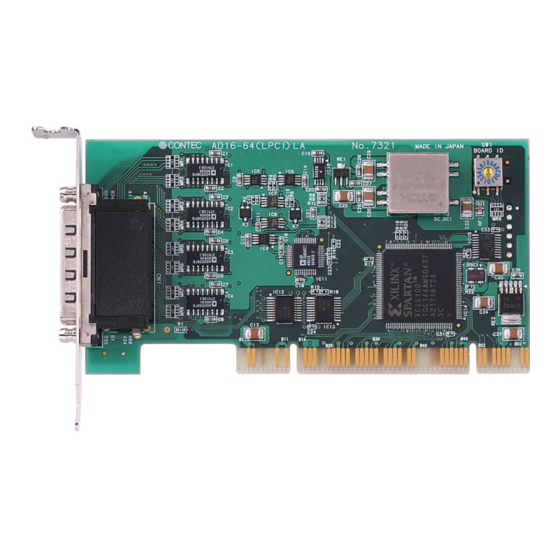
1. Before Using the Product About the Board The < AD16-64(LPCI)LA > is a PCI bus compatible interface board with 64 high-precision, 16-bit analog input channels, digital input and output channels (4 channels each), and a 32-bit counter (1 channel) This product supports a Low Profile size slot and, if replaced with the supplied bracket, supports a standard size slot, too. -
Page 9: Support Software
(DLL). Various sample programs such as Visual Basic and Visual C++, etc and diagnostic program *1useful for checking operation is provided. For more details on the supported OS, applicable language and new information, please visit the CONTEC’s Web site. Linux version of analog I/O driver... -
Page 10: Cable & Connector (Option)
*5 Can be used in CNA channels 0 - 7 or CNB channels 32 - 39. For details on the range channels available to each terminal panel, see Figure 3.2 "Connecting example of option". Check the CONTEC’s Web site for more information on these options. AD16-64(LPCI)LA... -
Page 11: Customer Support
You can download updated driver software and differential files as well as sample programs available in several languages. Note! For product information Contact your retailer if you have any technical question about a CONTEC product or need its price, delivery time, or estimate information. Limited Three-Years Warranty CONTEC products are warranted by CONTEC CO., LTD. -
Page 12: Safety Precautions
WARNING indicates a potentially hazardous situation which, if not avoided, could WARNING result in death or serious injury. CAUTION indicates a potentially hazardous situation which, if not avoided, may CAUTION result in minor or moderate injury or in property damage. AD16-64(LPCI)LA... -
Page 13: Handling Precautions
Even when using the product continuously, be sure to read the manual and understand the contents. Do not modify the product. CONTEC will bear no responsibility for any problems, etc., resulting from modifying this product. Regardless of the foregoing statements, CONTEC is not liable for any damages whatsoever (including damages for loss of business profits) arising out of the use or inability to use this CONTEC product or the information contained herein. -
Page 14: Environment
(3) Store the package at room temperature at a place free from direct sunlight, moisture, shock, vibration, magnetism, and static electricity. Disposal When disposing of the product, follow the disposal procedures stipulated under the relevant laws and municipal ordinances. AD16-64(LPCI)LA... - Page 15 1. Before Using the Product AD16-64(LPCI)LA...
-
Page 16: Setup
For setting up software other than API-PAC(W32), refer to the manual for that software. See also the following parts of this manual as required. This chapter Step 2 Setting the Hardware This chapter Step 3 Installing the Hardware Chapter 3 External Connection Chapter 6 About Hardware AD16-64(LPCI)LA... -
Page 17: Using The Board Under An Os Other Than Windows
About Software Chapter 6 About Hardware For using the board under an OS other than Windows and Linux, see the following parts of this manual. This chapter Step 2 Setting the Hardware Chapter 3 External Connection Chapter 6 About Hardware AD16-64(LPCI)LA... -
Page 18: Step 1 Installing The Software
OS used, the basic procedure is the same. Which Driver to Use CONTEC has two analog I/O drivers: “API-AIO(WDM)” and “API-AIO(98/PC)”. API-AIO(WDM) is a new driver for analog I/O under Windows. This driver was developed to be easier to use and to provide additional functions above those provided by the previous API-AIO(98/PC) driver. -
Page 19: Starting The Install Program
(2) The API-PAC(W32) Installer window appears automatically. If the panel does not appear, run (drive letter):\AUTORUN.exe. (3) Click on the [Install the drivers] button. CAUTION Before installing the software in Windows XP, 2000, or NT, log in as a user with administrator privileges. AD16-64(LPCI)LA... - Page 20 Clicking the [Details] button displays detailed information about API-AIO(WDM) and API-AIO(98/PC). Run the installation (1) Complete the installation by following the instructions on the screen. (2) The Readme file appears when the installation is complete. You have now finished installing the software. AD16-64(LPCI)LA...
-
Page 21: Step 2 Setting The Hardware
The replacing method is as follows : Standard size bracket - Remove the screws and replace it with the Standard size bracket. Low Profile size bracket Screws Use a standard screwdriver to attach and detach the screws. Figure 2.1. Replacing the Bracket AD16-64(LPCI)LA... -
Page 22: Parts Of The Board And Factory Defaults
Setting Procedure To set the board ID, use the rotary switch on the board. Turn the SW1 knob to set the board ID as shown below. BOARD ID Factory setting: (Board ID = 0) Figure 2.3. Board ID Settings (SW1) AD16-64(LPCI)LA... -
Page 23: Plugging The Board
Make sure that your PC or expansion unit can supply ample power to all the boards installed. Insufficiently energized boards could malfunction, overheat, or cause a failure. Power supply from the PCI bus slot at +5V is required. AD16-64(LPCI)LA... -
Page 24: Step 3 Installing The Hardware
In this case, you must check the resource settings. When Using API-AIO(WDM) (1) The “Found New Hardware Wizard” will be started. Select “Install from a list or specific location[Advanced]”, then click on the [Next] button. AD16-64(LPCI)LA... - Page 25 (2) Specify that folder on the bundled disk which contains the setup information (INF) file to register the board. * The name of the board you have just added is displayed. - AD16-64(LPCI)LA Source folder The setup information (INF) file is contained in the following folder on the bundled disk. \INF\WDM\AIO \INF\WDM\AIO You have now finished installing the hardware.
-
Page 26: Step 4 Initializing The Software
- AD16-64(LPCI)LA (2) The installed hardware appears under the CONTEC Devices node. Open the CONTEC Devices node and select the device you want to setup (the device name should appear highlighted). Click [Properties]. AD16-64(LPCI)LA... - Page 27 - AD16-64(LPCI)LA The initial device name that appears is a default value. You can use this default name if you wish. Make sure that you do not use the same name for more than one device.
-
Page 28: Step 5 Checking Operations With The Diagnosis Program
To check the analog input data, connect to an external signal source. The figure below shows an example of checking by connecting to an external signal. The example below is for analog input channel 0 on the AD16-64(LPCI)LA. Wiring Diagram <... -
Page 29: Using The Diagnosis Program
Click the [Diagnosis] button on the device property page to start the diagnosis program. * The name of the board you have just added is displayed. - AD16-64(LPCI)LA * The name of the board you have just added is displayed. - Page 30 Clicking the lower row of switches turns the digital output bits ON or OFF. Counter input Selecting a counter channel displays the count value and state of that counter channel. Clicking the zero clear button resets the count to zero. AD16-64(LPCI)LA...
- Page 31 Clicking [Diagnosis Report] prompts you to specify where to save the report text file. * The name of the board you have just added is displayed. - AD16-64(LPCI)LA (2) The diagnosis report contains the following data. Version of OS Device Information...
-
Page 32: Setup Troubleshooting
Refer to the source code for the sample programs. The OS does not boot correctly or does not detect the device correctly. Refer to the "Troubleshooting" section of API-AIO(WDM) HELP. If your problem cannot be resolved Contact your retailer. AD16-64(LPCI)LA... - Page 33 2. Setup AD16-64(LPCI)LA...
-
Page 34: External Connection
Two sets of cables are required depending on the number of channels used. Interface Connector (CNA, CNB) - Connector used HDRA-E68W1LFDT-SL equivalent [mfd.by HONDA] Applicable connector HDRA-E68MA1 equivalent [mfd.by HONDA] * Please refer to chapter 1 for more information on the supported cable and accessories. Figure 3.1. Interface Connector Shape AD16-64(LPCI)LA... - Page 35 Option Cable Termination Panel PCB68PS-**P Screw Terminal (M3 x 68P) EPD-68A Termination Panel Option Cable ADC-68M/96F AD16-64(LPCI)LA Screw Terminal (M3.5 x 96P, M3 x 96P) EPD-96, EPD-96A Option Cable PCA68PS-**P Screw Terminal (M2.5 x 96P) DTP-64(PC) BNC Terminal Unit BNC Terminal Unit...
-
Page 36: Connector Pin Assignment
Analog Ground Digital Output 02 32 66 Digital Output 03 (for AI) (for AI) Analog Ground Counter Gate Counter Count-up 2 N.C (for AI) Control Input Pulse Output Analog Ground Counter Clock Reserved 1 N.C (for AI) Input (Counter Input) AD16-64(LPCI)LA... - Page 37 If analog and digital ground are shorted together, noise on the digital signals may affect the analog signals. Accordingly, analog and digital ground should be separated. Leave "Reserved" pins unconnected. Connecting these pins may cause a fault in the board. AD16-64(LPCI)LA...
- Page 38 A46 N.C B03 N.C. Input) Analog Ground Counter Gate N.C. B02 N.C. (for AI) Control Input Counter Count-up N.C. A48 N.C B01 N.C. Pulse Output - [ ] shows the pin No. specified by HONDA TSUSHIN KOGYO CO., LTD. AD16-64(LPCI)LA...
- Page 39 If analog and digital ground are shorted together, noise on the digital signals may affect the analog signals. Accordingly, analog and digital ground should be separated. Leave "Reserved" pins unconnected. Connecting these pins may cause a fault in the board. AD16-64(LPCI)LA...
- Page 40 Count-up clock input signal for counter. Counter Output Count output signal. Digital Ground Common digital ground for digital I/O signals, external trigger inputs, Reserved Reserved pin N.C. No connection to this pin. Figure 3.5. Pin Assignment of interface connector (Differential Input) AD16-64(LPCI)LA...
- Page 41 If analog and digital ground are shorted together, noise on the digital signals may affect the analog signals. Accordingly, analog and digital ground should be separated. Leave "Reserved" pins unconnected. Connecting these pins may cause a fault in the board. AD16-64(LPCI)LA...
- Page 42 B03 N.C ( Counter Input ) Analog Ground Counter Gate B02 N.C ( for AI ) Control Input Counter Count-up A48 N.C B01 N.C Pulse Output - [ ] shows the pin No. specified by HONDA TSUSHIN KOGYO CO., LTD. AD16-64(LPCI)LA...
- Page 43 If analog and digital ground are shorted together, noise on the digital signals may affect the analog signals. Accordingly, analog and digital ground should be separated. Leave "Reserved" pins unconnected. Connecting these pins may cause a fault in the board. AD16-64(LPCI)LA...
-
Page 44: Analog Input Signal Connection
An input pin may fail to obtain input data normally when the signal source connected to the pin has high impedance. If this is the case, change the signal source to one with lower output impedance or insert a high-speed amplifier buffer between the signal source and the analog input pin to reduce the effect. AD16-64(LPCI)LA... -
Page 45: Differential Input
An input pin may fail to obtain input data normally when the signal source connected to the pin has high impedance. If this is the case, change the signal source to one with lower output impedance or insert a high-speed amplifier buffer between the signal source and the analog input pin to reduce the effect. AD16-64(LPCI)LA... -
Page 46: Digital I/O Signals, Counter Signals And Control Signals Connection
CAUTION Do not short the output signals to analog ground, digital ground, and/or power line. Doing so may damage the board. Reference For the operation timings for control signal input, see “Control Signal Timings” in Chapter 6 “Hardware”. AD16-64(LPCI)LA... - Page 47 3. External Connection AD16-64(LPCI)LA...
-
Page 48: Functions
1.Setting the Conversion Condititions Clock Resolution Start Condition Input Mode Stop Condition Channel Event Range Data transfer method Memory Repeat 2. Starting/Stopping Operation Start Stop 3.Monitoring the Status and Acquiring Data Status Sampling Repeat Data aquisition 4.Reset Status Memory AD16-64(LPCI)LA... -
Page 49: Setting The Conversion Conditions
When the device covers the range of 0 - 10V, the minimum unit of converted voltages is 10÷4096 ≈ 2.44mV. If the device has a resolution of 16-bit, it is 10÷65536 ≈ 0.153mV instead. AD16-64(LPCI)LA : The resolution is 16-bit. Input Mode ”Input Mode”... - Page 50 Software setup is not required as this board uses a fixed channel conversion priority. Range ”Range” means the range of voltages at which analog input can be performed Software setup of the range is not required as this board uses a fixed range of voltages. : ±10V AD16-64(LPCI)LA AD16-64(LPCI)LA...
- Page 51 The device buffer mode provides function that allows the number of items of conversion data using the number of sampling times as a unit to obtain the number of items of conversion data directly from the voltage. Device buffer mode AD16-64(LPCI)LA...
- Page 52 The ring memory is used to obtain data where conversion has stopped due to some event, usually without obtaining data in the normal state. AD16-64(LPCI)LA...
- Page 53 The sampling clock controls the sampling frequency. You can select both the internal sampling clock and external sampling clock. Internal sampling clock The clock signal from the on-board clock generator is used. External sampling clock The edge of the digital signal input from an external device is used for the sampling clock. AD16-64(LPCI)LA...
- Page 54 The board starts waiting for an external control signal as soon as the operation start command is output. Sampling and data transfer to memory start when the specified edge (rising edge or falling edge) is input from the external control signal. AD16-64(LPCI)LA...
- Page 55 The board starts waiting for an external control signal as soon as the operation start command is output. Sampling and data transfer to memory start when the specified edge (rising edge or falling edge) is input from the external control signal. AD16-64(LPCI)LA...
-
Page 56: Starting/Stopping Operation
AD conversion error event This event occurs when conversion stops due to an AD conversion error. 2. Starting/Stopping Operation Sampling is started by the software command. Once started, sampling can be stopped by the software command at any timing. AD16-64(LPCI)LA... -
Page 57: Monitoring The Status And Acquiring Data
ON. This error stops sampling. Sampling The number of sampled items of input data stored in memory can be obtained by the software command. Repeat The current repeat count can be obtained by the software command. AD16-64(LPCI)LA... - Page 58 When data is acquired from the memory, the free memory space increases by that data size. When data is acquired next, the oldest one of the existing data items is taken from the memory in the same way. The FIFO memory deletes data once that data is acquired. AD16-64(LPCI)LA...
- Page 59 (shaded portion below). The larger the number of samples taken, the older the data item acquired first. As the ring memory retains data even after that data is acquired, you can fetch the same data any number of times. AD16-64(LPCI)LA...
-
Page 60: Reset
Resets the conversion data in memory. Resets the repeat count to 0. Resets the sampling count to 0 when a stop trigger is input. Resets the buffer overflow status. Resets the status information for the specified data save count. AD16-64(LPCI)LA... -
Page 61: Counter Function
Input signal The external clock can be selected as the counter input signal. Digital filter A digital filter can be used on external input bits. The filter time can be set to "don't use", 1 µ s by software. AD16-64(LPCI)LA... -
Page 62: Starting/Stopping Operation
Execution of driver processing may not be able to keep up if multiple count match events occur within a short time period. In this case, the counter operation error status turns ON and counter operation stops. Data acquisition The current count value can be read using a software command. AD16-64(LPCI)LA... -
Page 63: Reset
4. Functions 4.Reset Various states can be reset by executing the following reset commands: Counter reset Resets the counter. This restores the counter to its state after power on. Status Resets the compare count match status and overrun status. AD16-64(LPCI)LA... -
Page 64: Digital Input Function
Byte data = 05(5H) Bit 3 Bit 2 Bit 1 Bit 0 0(OFF) 1(ON) 0(OFF) 1(ON) Digital filter A digital filter can be used on the input bits. The filter time can be set to "don't use", 1 µ s by software. AD16-64(LPCI)LA... -
Page 65: Digital Output Function
0 and 15. Ex. Output of bit 3 (ON), bit 2(OFF), bit 1 (ON), bit 0 (OFF) Byte data = 10(AH) Bit 3 Bit 2 Bit 1 Bit 0 0(OFF) 1(ON) 0(OFF) 1(ON) AD16-64(LPCI)LA... -
Page 66: About Software
|––WDM |––Win2000 |––Win95 |––linux Linux driver file |––cnt |––dio |––…… | ––Readme Readme file for each driver | ––Release Driver file on each API-TOOL |––API_NT (For creation of a user-specific install program) |––API_W95 | ––UsersGuide Hardware User's Guide(PDF files) AD16-64(LPCI)LA... -
Page 67: About Software For Windows
Reference”, “Sample Programs”, “Tutorial”, “FAQs”and “Troubleshooting”. Use them for program development and troubleshooting. Accessing the Help File (1) Click on the [Start] button on the Windows taskbar. (2) From the Start Menu, select “Programs” – “CONTEC API-PAC(W32)” – “AIOWDM” – “API-AIO(WDM) HELP” to display help information. AD16-64(LPCI)LA... -
Page 68: Using Sample Programs
The sample programs are stored in \Program Files\CONTEC\API-PAC(W32)\AIOWDM\Samples. Running a Sample Program (1) Click on the [Start] button on the Windows taskbar. (2) From the Start Menu, select “Programs” – “CONTEC API-PAC(W32)” – “AIOWDM” – “SAMPLE…”. (3) A sample program is invoked. - Page 69 Perform analog output using a callback routine Digital I/O - DioBit Perform digital I/O using bit values - DioByte Perform digital I/O using byte values Counter/Timer - Counter General purpose counter - Interval Interval timer - Watch Stopwatch timer Others - Convert Data conversion AD16-64(LPCI)LA...
-
Page 70: Usage Of Utility Program
* The name of the board you have just added is displayed. - AD16-64(LPCI)LA Procedure (1) Chose the measure device from device list. (2) Click the button written with the function name to measure the execution speed of the function. - Page 71 * The name of the board you have just added is displayed. - AD16-64(LPCI)LA The number of channels used, the internal/external clock, the conversion speed, and the sampling frequency at which an event generates can be set. Since the notification of a sampling clock error event is sent, please make use of it for the conversion spec measurement under various conversion conditions.
- Page 72 Moreover, the cause by noise etc. is also concerned. Buffer overflow : The memory overflows since the conversion speed is too fast compared with the one at which data is inputted. (4) Click the “stop” button, and measurement stops. AD16-64(LPCI)LA...
-
Page 73: Uninstalling The Driver Libraries
From the Start Menu, select “Settings” – “Control Panel”. (2) Double-click on “Add or Remove Programs” in the Control Panel. (3) Select "CONTEC API-AIO(WDM) driver" and "CONTEC API-AIO(WDM) VerX.XX (Development environment)" from the list of applications. Click the [Change or Remove Programs] button. -
Page 74: About Software For Linux
# mount /dev/cdrom /mnt/cdrom Mount the bundled disk. # cp /mnt/cdrom/linux/aio/caioXXX.tgz ./ Copy the compressed file. # tar xvfz caioXXX.tgz Decompress the compressed file....# cd contec/caio # make Compile the file....# make install Install....# cd config # ./config... -
Page 75: Accessing The Help File
Sample programs for each language are contained in the contec/caio/samples directory. For compiling them, refer to the manual for the desired language. Uninstalling the driver To uninstall the driver, use the uninstall shell script contained in the contec/caio directory. For details, check the contents of the script. AD16-64(LPCI)LA... -
Page 76: About Hardware
This chapter provides hardware specifications and hardware-related supplementary information. For detailed technical information For further detailed technical information ("Technical Reference" including the information such as an I/O map, configuration register, etc.), visit the Contec's web site (http://www.contec.com/support/) to call for it. Hardware specification Table 6.1. - Page 77 *3: This board requires +5V power supply from expansion slots (it does not operate in the environment of only +3.3V power supply). Board Dimensions 121.69(L) [mm] The standard outside dimension(L) is the distance from the end of the board to the outer surface of the slot cover. AD16-64(LPCI)LA...
-
Page 78: Block Diagram
Figure 6.1 is a circuit block diagram of this board. 4 Digital Inputs / 4 Digital Outputs 64 single-end External Trigger Inputs 32 differential Counter Input / Output Analog Inputs Multiplexer Buffer Amplifer Converter DC/DC FPGA converter PCI Bus Figure 6.1. Block Diagram AD16-64(LPCI)LA... -
Page 79: Control Signal Timings
Set up time of sampling stop (Rising edge) nsec Hold time of sampling stop (Rising edge) nsec Set up time of sampling stop (Falling edge) nsec Hold time of sampling stop (Falling edge) nsec CAUTION The times listed in Table 6.2 are for standard operating conditions. AD16-64(LPCI)LA... -
Page 80: Control Signal Timings For Analog Output
Time Unit Set up time of counter input (Rising edge) nsec Hold time of sampling start (Rising edge) nsec Pulse width of counter output signal 1000 nsec CAUTION The times listed in Table 6.3 are for standard operating conditions. AD16-64(LPCI)LA... -
Page 81: About Calibration
Click the [Calibration] button on the property page for the device to start the calibration program. * The name of the board you have just added is displayed. - AD16-64(LPCI)LA Proceed with connecting the calibration equipment and performing the calibration in accordance with the instructions displayed by the calibration program. Analog input calibration Analog input calibration requires a reference voltage generator. - Page 83 December 2017 Edition 3-9-31, Himesato, Nishiyodogawa-ku, Osaka 555-0025, Japan https://www.contec.com/ No part of this document may be copied or reproduced in any form by any means without prior written consent of CONTEC CO., LTD. [12152017] [10122005] Management No. A-51-097 [12152017_rev4] Parts No.
Need help?
Do you have a question about the AD16-64(LPCI)LA and is the answer not in the manual?
Questions and answers