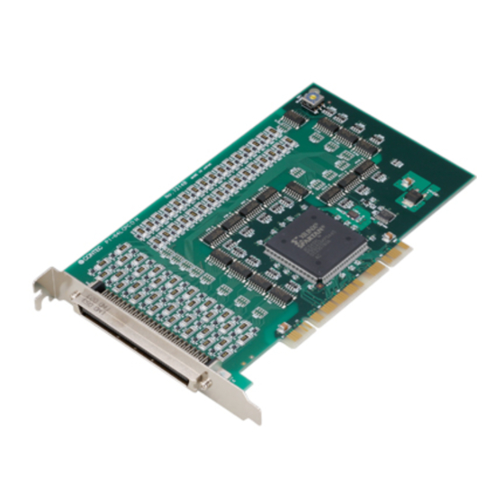
Digital i/o board with opto-isolation for pci
pio-32/32l(pci)h
digital input board with opto-isolation for pci
pi-64l(pci)h
digital output board with opto-isolation for pci
po-64l(pci)h
Digital i/o board with opto-isolation for pci
pio-32/32l(pci)h
digital input board with opto-isolation for pci
pi-64l(pci)h
digital output board with opto-isolation for pci
po-64l(pci)h (71 pages)
Digital i/o board with opto-isolation for pci
pio-32/32l(pci)h
digital input board with opto-isolation for pci
pi-64l(pci)h
digital output board with opto-isolation for pci
po-64l(pci)h (71 pages)
Digital i/o board with opto-isolation for pci, digital input board with opto-isolation for pci, digital output board with opto-isolation for pci (71 pages)


Need help?
Do you have a question about the PI-64L Series and is the answer not in the manual?
Questions and answers