Table of Contents
Advertisement
Quick Links
PC-HELPER Series
Reference Manual
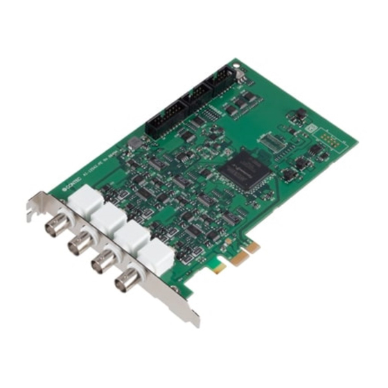
10MSPS 12-bit Analog Input Board for PCI Express
AI-1204Z-PE
CONTENTS
Introduction .................................................................. 5
Safety Precautions .................................................... 13
Setup ............................................................................. 19
Installation ................................................................... 33
Software ....................................................................... 42
Function ....................................................................... 47
Appendix ...................................................................... 72
Customer Support and Inquiry ............................ 82
Advertisement
Table of Contents

Related Manuals for Contec PC-HELPER Series


Summary of Contents for Contec PC-HELPER Series
- Page 1 PC-HELPER Series Reference Manual 10MSPS 12-bit Analog Input Board for PCI Express AI-1204Z-PE CONTENTS Introduction ..............5 Safety Precautions ............ 13 Setup ................19 Installation ..............33 Software ............... 42 Function ............... 47 Appendix ..............72 Customer Support and Inquiry ......82...
-
Page 2: Table Of Contents
Table of Contents Introduction ..............5 1. Related Manuals ..............................6 2. About the Product ..............................7 3. Features ..................................8 4. Product Configuration List ..........................10 5. Support Software ..............................11 6. Optional Products..............................12 Safety Precautions ............13 1. Safety Information ............................... 14 2. - Page 3 Table of Contents 2. Signal Layout on the Interface Connector ..................35 2. Connecting Analog Input Signal ........................38 1. Single-ended Input............................38 3. Connecting Digital I/O & Control Signals ....................39 1. Digital I/O signals and Control signals Connection ................ 39 4.
- Page 4 Table of Contents Customer Support and Inquiry ........82 1. Services ..................................83 — 4 —...
-
Page 5: Introduction
Introduction This section provides necessary information of the product such as the outline, bundled items and manuals before actual use. — 5 —... -
Page 6: Related Manuals
Reference Manual Read this when This describes the hardware Download from (This Document) operating the product. aspects such as functions the Contec and settings. website (PDF) Download Manuals Download the manuals accordingly from the following URL. https://www.contec.com/download/ Download — 6 —... -
Page 7: About The Product
— — Introduction AI-1204Z-PE Reference Manual 2. About the Product This product is a PCI Express bus-compliant interface board used to provide an analog signal input function on a PC. Maximum conversion speed is 10MSPS (100nsec), with simultaneous sampling of four channels at a same time. -
Page 8: Features
A synchronization control connector is provided for synchronized control of up to 16 boards. This means the number of channels can be increased simply by adding boards. It is also easy to synchronize operation with other CONTEC boards that have a synchronization control connector. - Page 9 Windows compatible driver software is provided Using the driver software API-AIO(WDM) , which can be downloaded from the CONTEC website, makes it possible to create applications of Windows. In addition, a Diagnostic Program to confirm the hardware operations is included in the software as well.
-
Page 10: Product Configuration List
— — Introduction AI-1204Z-PE Reference Manual 4. Product Configuration List The product consists of the items listed below. Check, with the following list, that your package is complete. If you discover damaged or missing items, contact your retailer. Product…1 Setup Guide…1 Warranty Certificate…1 Serial Number Label…1 Synchronization... -
Page 11: Support Software
AI-1204Z-PE Reference Manual 5. Support Software You can use CONTEC support software according to your purpose and development environment. For more details on the supported OS, applicable languages, or to download the latest version of software, visit the CONTEC Web site. -
Page 12: Optional Products
General Purpose Terminal (M3 x 15P) FTP-15 *3 DT-E3 is required. It is required only when FTP-15 is used. DT-E3 and PCB15PS-1.5P optional cable is required separately. Visit the CONTEC website for the latest optional products. https://www.contec.com/ Website — 12 —... -
Page 13: Safety Precautions
Safety Precautions Understand the following definitions and precautions to use the product safely. Never fail to read them before using the product. — 13 —... -
Page 14: Safety Information
— — Safety Precautions AI-1204Z-PE Reference Manual 1. Safety Information This document provides safety information using the following symbols to prevent accidents resulting in injury or death and the destruction of equipment and resources. Understand the meanings of these labels to operate the equipment safely. DANGER DANGER indicates an imminently hazardous situation which, if not avoided, will result in death or serious injury. -
Page 15: Handling Precautions
quality improvement. Even when using the product continuously, be sure to read the manual and understand the contents. Do not modify the product. CONTEC will bear no responsibility for any problems, etc., resulting from modifying this product. Regardless of the foregoing statements, CONTEC is not liable for any damages whatsoever ... -
Page 16: En55032Class A Notice
— — Safety Precautions AI-1204Z-PE Reference Manual 1. EN55032Class A Notice Warning: Operation of this equipment in a residential environment could cause radio interference. — 16 —... -
Page 17: Environment
— — Safety Precautions AI-1204Z-PE Reference Manual 3. Environment Use this product in the following environment. If used in an unauthorized environment, this product may overheat, malfunction, or cause a failure. Operating temperature -20 - 60ºC Humidity 10 - 90%RH (No condensation) Corrosive gases None Floating dust particles... -
Page 18: Disposal
— — Safety Precautions AI-1204Z-PE Reference Manual 6. Disposal When disposing of the product, follow the disposal procedures stipulated under the relevant laws and municipal ordinances. — 18 —... -
Page 19: Setup
Setup This section explains how to set up this product. — 19 —... -
Page 20: What Is Setup
— — Setup AI-1204Z-PE Reference Manual 1. What is Setup? Setup means a series of steps to take before the product can be used. Different steps are required for driver software and hardware. The setup procedure varies with the OS or driver software used. 1. -
Page 21: Driver Software Installation
Although some user interfaces are different depending on the OS used, the basic procedure is the same. For detailed OS installation procedure, refer to Help (APITOOL.chm) in the folder that installed the development environment package from CONTEC website. 1. Starting Up the Install Program Download the API-AIO(WDM) from CONTEC website. -
Page 22: Hardware Setting
— — Setup AI-1204Z-PE Reference Manual 3. Hardware Setting This section describes how to set up the product and how to connect it to a PC. 1. Nomenclature of Product Components Component names of the product are shown in the figure below. Name Name Interface Connector... -
Page 23: Termination Resistor Setting Switch
— — Setup AI-1204Z-PE Reference Manual 2. Termination Resistor Setting Switch The termination resistor setting switch is used to insert the termination resistor. Set up the termination resistor if suitable for the device to which you are connecting. This product has internal 50Ω (±1%) termination resistors. SW4 sets the resistor for channel 0, SW3 for channel 1, SW2 for channel 2, and SW1 for channel 3. -
Page 24: Sync Signal Control Connectors
— — Setup AI-1204Z-PE Reference Manual 4. Sync Signal Control Connectors The product indicates its operation state by means of light emitting diodes. The LED indicates as listed below. — 24 —... -
Page 25: Hardware Installation
— — Setup AI-1204Z-PE Reference Manual 4. Hardware installation Under Windows, the peripherals need to be recognized by the OS. This is called hardware installation. When using multiple products, install one product at a time. Complete the setup of the product before starting to install the next one. -
Page 26: Turning On The Pc
— — Setup AI-1204Z-PE Reference Manual 2. Turning on the PC Turn on the power to your PC. CAUTION The board cannot be properly installed unless the resources (I/O addresses and interrupt level) for the board can be allocated. Before attempting to install the board, first determine what PC resources are free to use. -
Page 27: Driver Software Initialization
For other than Windows 10, From the [Control Panel], select the [Hardware and Sounds] or the [System] and then select the [Device Manager]. The installed hardware appears under the CONTEC Devices node. Open the CONTEC Devices node and select the device you want to setup. Click the [Properties]. — 27 —... - Page 28 — — Setup AI-1204Z-PE Reference Manual The property page for the device opens. Enter the device name in the Common Settings tab page and then click the [OK]. The device name you set here is used later when programming. * The initial device name that appears is a default value. You can use this default name if you wish. * Make sure that you do not use the same name for more than one device.
-
Page 29: Operation Check
— — Setup AI-1204Z-PE Reference Manual 6. Operation Check You must make sure that this product and driver software operate properly. By taking this step, you can be certain that this product has been set up appropriately. 1. Check Method Connect the product to an external target device to test the communication and check the execution environment. - Page 30 — — Setup AI-1204Z-PE Reference Manual Checking Functions The main dialog box of the Diagnosis Program appears. You can check the current operation states of the product in the following boxes: Analog input Select the input channel and input type from the lists. Input data is plotted on a graph.
- Page 31 — — Setup AI-1204Z-PE Reference Manual Diagnosis Report Clicking on [Diagnosis] displays detailed data including product settings and the diagnosis results while saving them in text format. The diagnosis program performs the presence or absence of the product, driver file test, the board setting test, and so on.
-
Page 32: Setup Troubleshooting
— — Setup AI-1204Z-PE Reference Manual 7. Setup Troubleshooting 1. Examples and Solution Data input or output does not operate correctly Run the diagnosis program to check that the device is registered and whether any initialization errors have occurred. Is there a problem with the device settings, wiring, or similar? Check the I/O range setting. -
Page 33: Installation
Installation This section describes how to connect to an external device with a cable. — 33 —... -
Page 34: Connecting To An External Device
— — Installation AI-1204Z-PE Reference Manual 1. Connecting to an External Device 1. Connecting an Interface Connector To connect an external device to this product, plug the cable from the device into the interface connector (CN1, CN2, CN3, CN4, CN5) shown below. This product has five interface connectors: the (CN1, CN2, CN3, CN4, BNC connector) for analog inputs and the (CN5, 16-pin pin-header connector) for digital inputs/outputs. -
Page 35: Signal Layout On The Interface Connector
— — Installation AI-1204Z-PE Reference Manual 2. Signal Layout on the Interface Connector Layout on the Interface Connector(CN1, CN2, CN3, CN4) Signal name Description Analog Input0 - Analog Input3 Analog input signals. The numbers correspond to channel numbers. Analog Ground Analog input signals. - Page 36 — — Installation AI-1204Z-PE Reference Manual Layout on the Interface Connector(CN5) Signal name Signal name Number Number Digital Output 0 Digital Output 1 Digital Output 2 Digital Output 3 Digital Ground Digital Input 0 Digital Input 1 Digital Input 2 Digital Input 3 External Start Trigger Input External Stop Trigger Input...
- Page 37 — — Installation AI-1204Z-PE Reference Manual Optional cable DT-E3 Signal name Signal name Number Number Digital Output 0 Digital Output 1 Digital Output 2 Digital Output 3 Digital Ground Digital Input 0 Digital Input 1 Digital Input 2 Digital Input 3 External Start Trigger Input External Stop Trigger Input External Sampling Clock Input...
-
Page 38: Connecting Analog Input Signal
— — Installation AI-1204Z-PE Reference Manual 2. Connecting Analog Input Signal 1. Single-ended Input The following figure shows an example of shielded cable connection. For the CN1 each analog input, connect the core wire to the signal line and connect the shielding to ground. CAUTION Do not touch the external connector (BNC connector) when the power is on. -
Page 39: Connecting Digital I/O & Control Signals
— — Installation AI-1204Z-PE Reference Manual 3. Connecting Digital I/O & Control Signals Digital I/O signals can be used as control I/O signals (external trigger input signals, sampling clock input signals, etc.). The following section shows examples of how to connect signals. 1. -
Page 40: Synchronization Control Connectors
— — Installation AI-1204Z-PE Reference Manual 4. Synchronization Control Connectors 1. Synchronization Control Connectors Controlling simultaneous operations between boards or controlling in sync with events is in part dependent on software performance. In order to enhance the reliability of the entire system and to solve these problems, the board is equipped with SC (Synchronization Control) connectors. -
Page 41: Connecting The Sync Connectors (Cn6, Cn7)
— — Installation AI-1204Z-PE Reference Manual Example 2: When controlling slave operations with master's internal events By outputting an internal event (interrupt) occurring on the master board, the slaves can start operating in sync with that signal. Connect the SC cable. Designate master/slave with the software. -
Page 42: Software
Software This section describes analog input and output driver for Windows developed by CONTEC. — 42 —... -
Page 43: Analog I/O Driver For Windows
1. Accessing the Help File It might be slightly different depending on the installed driver (development environment) version. From “Start” menu on Windows task bar, click on [CONTEC API-PAC(W32)]-[API-TOOL(WDM) HELP] to display help information. If this link cannot be found, go to the “Start” menu on Windows task bar, click “CONTEC “API-AIO(WDM) “... -
Page 44: Running A Sample Program
— Software AI-1204Z-PE Reference Manual 3. Running a Sample Program From the Start Menu on the Windows taskbar, go to “Programs” - “CONTEC API-AIO(WDM) for API- PAC(W32)” and select the sample programs. Sample Programs - Examples Analog input Simple sample program SingleAi Perform single analog input from specified channel ... -
Page 45: Distributing Developed Application
— — Software AI-1204Z-PE Reference Manual 4. Distributing Developed Application Please distribute the developed application with API-AIO(WDM) driver. The developed applications (driver included) can freely be distributed. 5. Use of Utility Program Refer to the Help in the Analog I/O driver for details of the Utility Program. ... -
Page 46: Uninstalling The Driver Software
Uninstall of Device Driver Use [Control Panel] - [Programs and Features] to uninstall the development environment. Select [Windows driver package - CONTEC (Caio) Contec] and then click [Uninstall/Change]. Uninstall the Development Environment Use [Control Panel] - [Programs and Features] to uninstall the development environment. -
Page 47: Function
Function This section describes the features achieved by combining hardware and driver functions. — 47 —... -
Page 48: Analog Input Function
— — Function AI-1204Z-PE Reference Manual 1. Analog Input Function The product converts analog signals to digital data according to the resolution and stores it in memory. You can set a variety of conditions for analog input, including the input channel, sampling period, and sampling start/stop conditions. -
Page 49: Setting The Conversion Conditions
— — Function AI-1204Z-PE Reference Manual 1. Setting the Conversion Conditions First, set the conditions for executing analog input. Resolution “Resolution” signifies the number of bits used by an analog input device to represent analog signals. The higher the resolution, the more finely the voltage range is segmented, allowing the device to convert analog values to digital equivalents more precisely. - Page 50 — — Function AI-1204Z-PE Reference Manual Channel “Channel” represents each channel No. of analog input signal. For channel numbers, see “Connecting an Interface Connector(Page34)”. Any number of analog inputs can be performed by setting up channels with software. There are 0-3 channels in this product. ...
- Page 51 — — Function AI-1204Z-PE Reference Manual Data Transfer Method You can select between device buffer mode, which saves conversion data in a conversion data memory area either on the device or in the driver, or user buffer mode which saves the conversion data in application memory.
- Page 52 — — Function AI-1204Z-PE Reference Manual Memory Format You can select memory format by software. FIFO format In the FIFO (First In First Out) format, conversion data are read from memory in the same order in which they were written to the memory. Conversion data are fed out of the memory sequentially, where the oldest one is always read from the memory.
- Page 53 — — Function AI-1204Z-PE Reference Manual Clock The sampling clock controls the sampling frequency. You can select either the internal sampling clock, or external sampling clock, or the output of the event controller. Internal sampling clock The clock signal from the installed clock generator is used. External sampling clock The edge of the digital signal input from an external device is used for the sampling clock.
- Page 54 — — Function AI-1204Z-PE Reference Manual Start Condition The condition for controlling the start of sampling can be selected from among software, conversion data comparison and an external trigger. The conditions for controlling the start and stop of sampling are completely independent of each other;...
- Page 55 — — Function AI-1204Z-PE Reference Manual Conversion data in-range comparison The in-range compare start condition is established when the level on the specified analog channel enters the range specified by level 1 and level 2. Saving of conversion data to memory is performed for the sample points indicated by the black dots.
- Page 56 — — Function AI-1204Z-PE Reference Manual Stop Condition The condition for controlling the stop of sampling can be selected from among the last sampling count, conversion data comparison, an external trigger, and software abort. The product stops sampling whenever an error occurs irrespective of the stop condition setting. Software Sampling continues indefinitely in this mode.
- Page 57 — — Function AI-1204Z-PE Reference Manual If you set the level comparison directions to both directions, the start condition is satisfied when the analog signal passes the level both in the rising and falling directions. Conversion data in-range comparison The in-range compare stop condition is established when the level on the specified analog channel enters the range specified by level 1 and level 2.
- Page 58 — — Function AI-1204Z-PE Reference Manual Delayed sampling Delayed sampling is performed after the sampling stop condition is satisfied. When a sampling stop condition other than the software abort command is satisfied, this product performs sampling for the specified number of times of delayed sampling to store input data to memory.
-
Page 59: Starting/Stopping Operation
— — Function AI-1204Z-PE Reference Manual Event “Event” works as a function for reporting the occurrence of a certain device state to the application. The following events can be used in combination depending on the specifications and purpose of the application. -
Page 60: Monitoring The Status And Acquiring Data
— — Function AI-1204Z-PE Reference Manual 3. Monitoring the Status and Acquiring Data Software commands are used to monitor the operation status of the device and to acquire conversion data from memory. Status monitoring and data acquisition can be performed even during sampling. - Page 61 — — Function AI-1204Z-PE Reference Manual AD conversion error If the “device operating” status remains ON (without terminating conversion) for an extended period of time, the driver regards that state as an operation error and sets this status to ON. This error stops sampling.
- Page 62 — — Function AI-1204Z-PE Reference Manual Data acquisition in FIFO format When FIFO memory is used, the oldest data is always read first. The following sketch shows an image of data acquisition in FIFO format. When data is acquired from the memory, the free memory space increases by that data size. When data is acquired next, the oldest one of the existing data items is taken from the memory in the same way.
- Page 63 — — Function AI-1204Z-PE Reference Manual Data acquisition in RING format When ring memory is used, data is read always with respect to the current input data write position. The following sketch shows an image of data acquisition in ring format. The sampling count obtained is always the number of times of sampling for up to the latest data (shaded portion below).
- Page 64 — — Function AI-1204Z-PE Reference Manual Data acquisition in user buffer When using a user buffer, the conversion data is transferred directly to application memory by the driver. The figure above shows how to set the data in the user buffer for the case when 2channels (0 and 1channel) are used.
- Page 65 — — Function AI-1204Z-PE Reference Manual Conversion data The following equation represents the relation between conversion data and voltage. Voltage or Current = Conversion data x (Max. range value - Min. range value) ÷ Resolution + Min. range value The value of resolution for the 12-bit device is 4096;...
-
Page 66: Reset
— — Function AI-1204Z-PE Reference Manual 4. Reset Various states can be reset by executing the following reset commands: Status This command resets the sampling clock error status and AD conversion error status. Memory This can only be used when the transfer mode is set to device buffer mode. This command resets the following memory related states. -
Page 67: Digital Input Function
— — Function AI-1204Z-PE Reference Manual 2. Digital Input Function 1. Input bit Individual digital input points are called input bits. When the number of input points of a device is 4, the bits are determined as bit 0 - bit 3. 2. -
Page 68: Digital Output Function
— — Function AI-1204Z-PE Reference Manual 3. Digital Output Function 1. Output bit Individual digital output points are called output bits. When the number of output points of a device is 4, the bits are determined as bit 0 - bit 3. 2. -
Page 69: Event Controller Function
— — Function AI-1204Z-PE Reference Manual 4. Event Controller Function 1. Overview of the event controller The event controller is used to determine how the control signals between the various functions are interlinked. Customizing the way in which the control signals are used allows more advanced operations to be implemented by synchronizing the different functions within a single device and by synchronizing operation between multiple devices. -
Page 70: Example Of Using The Event Controller
— — Function AI-1204Z-PE Reference Manual 2. Example of using the event controller The following example shows how to configure the event controller to synchronize analog input operation between two devices using the synchronization connector. Synchronizing between two devices is performed by connecting control signals from device 1 to device 2. - Page 71 — — Function AI-1204Z-PE Reference Manual Setting up the event controller (Device 2) The internal clock signal from device 1 is connected to synchronization bus master signal 2 which in turn is connected to synchronization bus slave signal 2 in the synchronization connector.
-
Page 72: Appendix
Appendix This section lists the specifications and the physical dimensions of the product. — 72 —... -
Page 73: Hardware Specification
— — Appendix AI-1204Z-PE Reference Manual 1. Hardware Specification Function Specifications (1/2) Item AI-1204ZPE Analog input Isolated specification Unisolated Input type Single-Ended Input Input channel Input range (when 50Ω termination setting disabled) Bipolar ±10V, ±5V, ±2.5V, ±1.25V or Unipolar 0 - +10V, 0 - +5V, 0 - +2.5V (when 50Ω... - Page 74 — — Appendix AI-1204Z-PE Reference Manual Function Specifications (2/2) Item AI-1204ZPE Digital input Number of input channels Input type Unisolated input (LVTTL level positive logic) Digital output Number of output channels Output format Unisolated output (LVTTL level positive logic) Bus master DMA channels section Transfer bus width...
- Page 75 — — Appendix AI-1204Z-PE Reference Manual Installation Environment Requirements Item AI-1204Z-PE Operating ambient temperature 0 - +50°C Operating ambient humidity 10 - 90%RH (No condensation) Floating dust particles Not to be excessive Corrosive gases None Line-noise Line noise AC Line/±2kV resistance Signal Line /±1kV(IEC61000-4-4 Level 3, EN61000-4-4 Level 3) Static...
-
Page 76: Physical Dimensions
— — Appendix AI-1204Z-PE Reference Manual 2. Physical Dimensions — 76 —... -
Page 77: Circuit Block Diagram
— — Appendix AI-1204Z-PE Reference Manual 3. Circuit Block Diagram — 77 —... -
Page 78: Control Signal Timings
— — Appendix AI-1204Z-PE Reference Manual 4. Control Signal Timings 1. Control Signal Timings for Analog Input AI-1204Z-PE is unrelated with the sampling clock, it is always sampled in each 100nsec. In a word, the conversion results from the A/D convertor are stored in an internal register once, the values are updated in each 100nsec. - Page 79 — — Appendix AI-1204Z-PE Reference Manual Control Signal Timings Parameter Symbol Time Unit Delay time from external sampling clock to data latch of the A/D converting data nsec register Set up time of sampling start (Rising edge) nsec Hold time of sampling start (Rising edge) nsec Set up time of sampling start (Falling edge) nsec...
-
Page 80: About Calibration
— — Appendix AI-1204Z-PE Reference Manual 5. About Calibration Although this product is calibrated before shipping, you can use the calibration program to calibrate analog input yourself. Starting the calibration program Click the [Calibration] button on the property page for the device to start the calibration program. *For module ID, the setting value of Module ID rotary switch is displayed. -
Page 81: Differences Between Ai-1204Z-Pe And Ai-1204Z-Pci
— — Appendix AI-1204Z-PE Reference Manual 6. Differences between AI-1204Z-PE and AI-1204Z-PCI Item AI-1204Z-PE AI-1204Z-PCI For analog (CN1,2,3,4) B-901W1AAN03 equivalent [mfd. DB-414K equivalent [mfd. BNC connector By INSERT ENTERPRISE] INSERT ENTERPRISE], Bus specification PCI Express Base Specification 32bit, 33MHz, Universal key Rev.2.0 x1 shapes supported Current consumption (Max.) - Page 82 Customer Support and Inquiry CONTEC provides the following support services for you to use CONTEC products more efficiently and comfortably. — 82 —...
- Page 83 — — Customer Support and Inquiry AI-1204Z-PE Reference Manual 1. Services CONTEC offers the useful information including product manuals that can be downloaded through the CONTEC website. Download https://www.contec.com/download/ You can download updated driver software, firmware, and differential manuals in several languages. Membership registration (myCONTEC) is required to use the services.
- Page 84 — — Customer Support and Inquiry AI-1204Z-PE Reference Manual Revision History MONTH YEAR Summary of Changes June 2020 The First Edition. — 84 —...
- Page 85 CONTEC CO., LTD. 3-9-31, Himesato, Nishiyodogawa-ku, Osaka 555-0025, Japan https://www.contec.com/ No part of this document may be copied or reproduced in any form by any means without prior written consent of CONTEC CO., LTD. AI-1204Z-PE Reference Manual NA07326 (LYYD272) 06262020_rev2...
Need help?
Do you have a question about the PC-HELPER Series and is the answer not in the manual?
Questions and answers