
Related Manuals for CNC4PC C11G


Summary of Contents for CNC4PC C11G
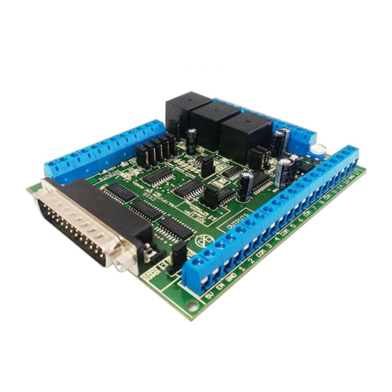
- Page 1 USER’S MANUAL VER.1 C11G- MULTIFUNTCION CNC BOARD Rev. 9 MARCH, 2017 User’s Manual Page i...
-
Page 2: Table Of Contents
USER'S MANUAL TABLE OF CONTENTS Contents Page # OVERVIEW ........................1 FEATURES ........................1 SPECIFICATIONS ......................2 BOARD DESCRIPTION ....................2 POWER TERMINALS AND CONFIGURATION JUMPERS ..........3 Power Terminal ......................3 External Enable Pin ....................4 Led Indicator ......................4 Safety Charge Pump “SCHP”. -
Page 3: Overview
OVERVIEW This card has been designed to provide a flexible interface and functions to your computer projects by using the parallel port or USB-based or Ethernet-based controller. This board comes as a response to many customers that have been asking for a faster way to connect devices and reduce the possibility of wiring errors. -
Page 4: Specifications
SPECIFICATIONS DIGITAL INPUT SPECIFICATIONS On-state voltage range 2 to 5V DC Maximum off-state voltaje 0.8V Maximum operation frequency 4 MHz Typical signal delay 10nS DIGITAL OUTPUT SPECIFICATIONS (5V power supply voltage) + Maximum output voltage 0.5V Typical output current 24mA Maximum off-state voltaje 0.44 V Maximum operation frequency... -
Page 5: Power Terminals And Configuration Jumpers
POWER TERMINALS AND CONFIGURATION JUMPERS Regulated +5VDC@ 1A is required to power this board. WARNING Check the polarity and voltage of the external power source and connect the 5VDC and GND. Overvoltage or reverse-polarity power applied to these terminals can cause damage to the board, and/or the power source. -
Page 6: External Enable Pin
External Enable Pin. The card must be provided with a 5VDC signal to enable operation. This feature has been added to externally control the status of the outputs. An external switch or a Safety Charge Pump can be added to provide the enabling signal. When the enable signal is not present, output signals send high impedance state. -
Page 7: Safety Charge Pump "Schp". (Pin 17)
Safety Charge Pump “SCHP”. (Pin 17). This board takes advantage of Mach ability to send a specific frequency through one of the pins of the parallel port when the program is in control of the system. CNC machinery can be very dangerous, and you could have a risk of the machine doing something different that what you intend the machine to do if the program loses control of your system. -
Page 8: Controller Selection Jumpers (Ieee1284)
Selecting the SCHP operation mode The Safety Charge Pump can be activated or deactivated depending on the jumper position 1-2: SCHP OFF 2-3: SCHP ON Note: When the Safety Charge Pump is activated, the EN terminal is active and a valid SCHP signal is present, pin 17 will go high. -
Page 9: Variable Speed Control
VARIABLE SPEED CONTROL This function lets you control your spindle with PWM signal. It converts the PWM signal into an analog (0-10VDC). This function can also be used on many DC motor controllers by replacing the potentiometer that controls the speed. Requirements: It requires a power supply external +12VDC@ 30mA for the analog output WARNING: To keep the output signals optoisolated, these must not have... - Page 10 Relay 1 and 2 They can be used to control the VFD. The relay specifications are shown in this table. ELECTROMECHANICAL RELAYS SPECIFICACTIONS Maximun Current (AC) 7A@240VAC; 10A@125VAC Maximun Current (DC) 15A@524VDC; 10A@28VDC Electromechanical Relays Specifications Replacing a Potentiometer: This circuit can be used to replace a potentiometer of DC moto. These speed controller circuits are very commonly used by SIEG, KB Electronics, and many other oriental machines.
-
Page 11: Electromechanical Relays. (Pin_1 Or Pin_17)
Electromechanical relays. (Pin_1 or Pin_17) This RELAY is activated with the PIN_1 or PIN_17, set jumper as sample in the image. PIN_1 PIN_17 Mechanical relays are very flexible because they can be used for AC or DC and come with NO and NC (Normally Open and Normally Closed) positions. The relay specifications are shown in the below table. -
Page 12: Functional Block Diagrams
FUNCTIONAL BLOCK DIAGRAMS Outputs 2-9 simplified functional block diagram Parallel Port circuit uses IEEE 1284 standard recommendation. The LEDs for the pins are driven by a separate buffer. Outputs 1, 14, 16 and 17 simplified functional block diagram Note: “Internal Enable” = “External Enable Pin” AND (“SCHP” OR “Bypassed SCHP”) The “Internal Enable”... -
Page 13: Input Simplified Functional Block Diagram
Input simplified functional block diagram Simplified functional block diagram for the inputs Selection Jumper PULL-UP or PULL-DOWN Pins 10,11,12,13 and 15 can be set to pull-up or pull-down by selecting the jumper in the appropriate position. The input pins can be set to be pulled up or down with a 4.7Kohm resistor. 1-2: PULL-UP 2-3: PULL- DOWN Pull up/down resistors determine the normal status of a pin when left in the air (not... -
Page 14: Wiring Diagrams
WIRING DIAGRAMS While this board supports only TTL +5VDC signals, different kind of sensors, switches using different voltages can be connected using the diagrams that follow: Note: The below wiring diagrams are examples, any input can be used for the connections. Note. - Page 15 Wiring diagram to connect in parallel NPN open collector proximity sensors Connecting NPN open collector proximity sensor with the C11GS R1 Value (12V) R1 Value (24V) Aprox. 10KΩ Aprox. 25KΩ Wiring diagram to connect NPN proximity sensors with internal pull up resistor Some NPN proximity sensor has a pull-up resistor (R1) internally.
- Page 16 Connecting NPN open collector proximity sensor with the C11GS (R1+R2) Value (12V) (R1+R2) Value (24V) Aprox. 10KΩ Aprox. 25KΩ Calculating the R1 value Note: Rx is the unknown resistor value. . (R/V) - R Where: is the external power supply voltage V is the voltage across the R resistor An external resistor and a voltmeter are required to calculate the internal resistor (Rx) value.
-
Page 17: Connecting Pnp Sensors
Connecting PNP sensors. Wiring diagram to connect PNP proximity sensors Connecting PNP proximity sensor with the C11GS R Value (12V) R Value (24V) Aprox. 10KΩ Aprox. 25KΩ User’s Manual Page 15... -
Page 18: Dimensions
DIMENSIONS All dimensions are in Millimeters Fixing holes (3.8mm). DISCLAIMER: Use caution. CNC machines can be dangerous machines. Neither DUNCAN USA, LLC nor Arturo Duncan are liable for any accidents resulting from the improper use of these devices. This board is not a fail-safe device and it should not be used in life support systems or in other devices where their failure or possible erratic operation could cause property damage, bodily injury or loss of life.
Need help?
Do you have a question about the C11G and is the answer not in the manual?
Questions and answers