Table of Contents
Advertisement
Advertisement
Table of Contents

Related Manuals for CNC4PC C25S


Summary of Contents for CNC4PC C25S
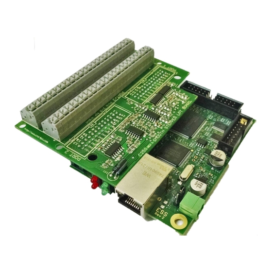
- Page 1 USER’S MANUAL C25S- SMOOTH STEPPER LPT BOARD Rev. 1 APR, 2016...
-
Page 2: Table Of Contents
USER'S MANUAL TABLE OF CONTENTS Page # Contents FEATURES ........................1 SPECIFICATIONS ......................1 FUNCTIONAL BLOCK DIAGRAMS ................2 Inputs 10, 11, 12 13 and 15 (Port 1 and Port 2) Schematic ........2 Inputs 2-9 (Port 2) Schematic ..................2 SET JUMPER IN THE S.S .................... -
Page 3: Features
• All TTL 5VDC signals. Interface directly with parallel port interface products and other CNC4PC cards. 5VDC (TTL) cards are very common among automation devices. • Input and output pins with close by ground connections. -
Page 4: Functional Block Diagrams
FUNCTIONAL BLOCK DIAGRAMS Inputs 10, 11, 12 13 and 15 (Port 1 and Port 2) Schematic Simplified functional block diagram Note: The Smooth Stepper includes an Schmitt Trigger in those input pins. Inputs 2-9 (Port 2) Schematic Using an RC Low Pass filter followed by a Schmitt Trigger gate will reduce the effect of the noise from driver or other devices. -
Page 5: Set Jumper In The S.s
SET JUMPER IN THE S.S WIRING DIAGRAMS Different kind of sensors and switches can be connected to inputs board, but this board support only TTL signal. If you need to connect devices that generates 12V or 24V signals in some cases is necessary add external resistors. Connecting Switches or push button. -
Page 6: Connecting Npn Sensors (For Any Input)
WIRING DIAGRAM TO CONNECT SWITCHES Connecting NPN sensors (For any input) Wiring diagram to connect NPN open collector proximity sensors WIRING DIAGRAM TO CONNECT IN PARALLEL NPN OPEN COLLECTOR PROXIMITY SENSORS Connecting NPN open collector proximity sensor with the C25 R1 Value (12V) R1 Value (24V) Aprox. - Page 7 Wiring diagram to connect NPN proximity sensors with internal pull up resistor Some NPN proximity sensors have an internal pull-up resistor (R1). It is necessary to know its value in order to safely connect the sensor with the BOB. Follow this recommendation: Connecting NPN open collector proximity sensor with the C25 (R1+R2) Value (12V)
-
Page 8: Connecting Pnp Sensors (For Any Input)
Where: is the external power supply voltage V is the voltage across the R resistor A voltmeter is required to calculate the internal resistor value (Rx). Do the connection as are shown in the figure above and do the calculations using the equation (1). Note. -
Page 9: Other Connection (For Any Input)
Other connection (For any input) Other connections can be implemented by setting the inputs with pull-up resistor. In this case connect an external 4.7KOhm resistor between the input terminal and the 5V terminal. Wiring diagram to do an “Auto Tool Zero” User’s Manual Page 7... -
Page 10: Dimensions
DIMENSIONS All dimensions are in Millimeters. DISCLAIMER Use caution. CNC machines can be dangerous machines. Neither DUNCAN USA, LLC nor Arturo Duncan are liable for any accidents resulting from the improper use of these devices. This product is not a fail-safe device and it should not be used in life support systems or in other devices where its failure or possible erratic operation could cause property damage, bodily injury or loss of life.
Need help?
Do you have a question about the C25S and is the answer not in the manual?
Questions and answers