Table of Contents
Advertisement
Quick Links
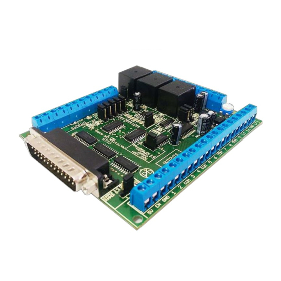
C11G (Rev.8.2) User Manual
C11G- MULTIFUNTCION CNC BOARD
1. Overview
This card has been designed to provide a flexible interface and functions to your
computer projects, by using the parallel port control software. This board comes as a
response to many customers that have been asking for a faster way to connect
devices and reduce the possibility of wiring errors.
2. Features
• IEEE 1284 Standard compatible.
Includes the circuitry recommended
by the IEEE 1284 Level 1 standards
for
bidirectional
communications between personal
computers and peripherals
• PULL-UP
or
selection for inputs.
Includes jumpers to select the best
input
configuration
application.
• Buffered
inputs
Outputs are buffered through the use
of high speed and high current
buffers allowing the card to output
the signals without using the power
from the parallel port. It can take the
+3.3 or +5vdc signal from the parallel
Revision: 01/27/2010
Rev. 8.2
User manual Rev. 2
•
parallel
PULL-DOWN
• Built-in Variable Speed Control.
for
your
and
outputs.
• Two
http://cnc4pc.com/TechDocs/C11GR8_2_User_Manual.pdf 1/21
port and deliver solid +5vdc at 24
milliamps.
Microcontroller based SCHP
This
board
comes
microcontroller
that
implementation
of
algorithm for sampling and analyzing
the SCHP signal.
It has an optoisolated analog 0-
10VDC output that will convert a step
signal into an analog signal that can
be used to command a commercial
VFD. This analog can be adjusted
using on-board potentiometer, so this
board can be adjusted to other
voltages.
Electromechanical
with NO and NC positions.
Mechanical relays are very flexible
because they can be used for AC or
DC and come with NO and NC
.
with
a
allows
the
a
complex
Relays
Advertisement
Table of Contents

Subscribe to Our Youtube Channel
Related Manuals for CNC4PC C11G


Summary of Contents for CNC4PC C11G
- Page 1 C11G (Rev.8.2) User Manual C11G- MULTIFUNTCION CNC BOARD Rev. 8.2 User manual Rev. 2 1. Overview This card has been designed to provide a flexible interface and functions to your computer projects, by using the parallel port control software. This board comes as a response to many customers that have been asking for a faster way to connect devices and reduce the possibility of wiring errors.
- Page 2 C11G (Rev.8.2) User Manual (Normally Open Normally once. The board requires +5vdc in Closed) positions. the EN pin. If it is not present, it will send all the outputs to ground. You • Status LEDs on all inputs and can use this to enable or disable the output connections.
-
Page 3: Functional Block Diagrams
C11G (Rev.8.2) User Manual 3. Specifications. DIGITAL INPUT SPECIFICATIONS On-state voltage range 2 to 5V DC Maximum off-state voltaje 0.8V Maximum operation frequency 4 MHz Typical signal delay 10nS DIGITAL OUTPUT SPECIFICATIONS Maximum output voltage (5V power supply voltage) + 0.5V... - Page 4 C11G (Rev.8.2) User Manual Fig. 1 Simplified functional block diagram for the outputs 2-9. Parallel Port coupling is done following IEEE 1284 standard recommendation. The indicator led is driven by a different buffer. 4.2 Outputs 1, 14, 16 and 17 simplified functional block diagram Fig.
-
Page 5: Special Functions
C11G (Rev.8.2) User Manual Fig. 3 Simplified functional block diagram for the inputs. Pins 10, 11, 12, 13 and 15 can be set to pull-down or pull-up by selecting the jumper in the appropriate position. The input pins can be set to be pulled up or down with a 4.7Kohm resistor. - Page 6 C11G (Rev.8.2) User Manual doing something different that what you intend the machine to do if the program loses control of your system. Mach be can be programmed in a way, so when it is “in control”, it delivers a 12.5 KHz signal through one of the pins. This card lets you use this signal to work as an On/Off switch for your system, enabling a powerful safety system for your equipment.
- Page 7 C11G (Rev.8.2) User Manual Selecting the SCHP operation mode. The Safety Charge Pump can be activated deactivated depending on the jumper position 1-2: SCHP OFF 2-3: SCHP ON Note: When the Safety Charge Pump is activated, the EN terminal is active and a valid SCHP signal is present, pin 17 will go high.
- Page 8 C11G (Rev.8.2) User Manual You will require a voltmeter to fine tune your system. Wiring: Before connecting anything, please be sure to read your VFD’s manual and make sure you understand all the safety issues. Please check the wiring guide and wiring samples here: http://cnc4pc.com/Tech_Docs/C6R5_WG.pdf...
- Page 9 C11G (Rev.8.2) User Manual Fig. 5. Spindle Setup screenshot. Go to Config / Motor Tuning / Spindle. On Steps per unit put 1,000, set velocity to maximum. For Acceleration, choose the acceleration that you feel comfortable with. Start slow, increase acceleration as you test your system. Under Step Pulse length, use a number from 3 to 5, but start with 3.
- Page 10 C11G (Rev.8.2) User Manual After configuring the Mach, these steps should be followed. Step 1. Ensure that all external power sources are set to OFF. Step 2. Connect the power supply to the Power Inputs Connectors (X1). Step 3. Turn on the external supplies Step 4.
-
Page 11: Using The Com Configuration Jumper
C11G (Rev.8.2) User Manual 6.4 Using the COM configuration jumper. This is for selecting the value to get at the COM terminals found next to step and direction terminals (Pin 2-9). Some drivers expect a ground, and others expect +5vdc. There is a jumper (X7) that allows you to select +5VDC or GND for the COM pins. -
Page 12: Wiring Diagrams
C11G (Rev. 8.2) User Manual 7. Wiring diagrams While this board supports only TTL +5VDC signals, different kind of sensors, switches using different voltages can be connected using the diagrams that follow: Note: The below wiring diagrams are an example, any input can be used for the connections. - Page 13 7.2 Connecting NPN sensors. Fig. 8 Wiring diagram to connect NPN open collector proximity sensors. Fig. 9 Wiring diagram to connect in parallel NPN open collector proximity sensors. Connecting NPN open collector proximity sensor with the C11G R1 Value (12V) R1 Value (24V) Aprox.
- Page 14 Some NPN proximity sensor has a pull-up resistor (R1) internally. It is necessary to know its value in order to connect safely the sensor with the BOB. Follow this recommendation: Connecting NPN open collector proximity sensor with the C11G (R1+R2) Value (12V) (R1+R2) Value (24V) Aprox.
- Page 15 C11G (Rev. 8.2) User Manual Calculating the R1 value. Note: Rx is the unknown resistor value. .(R/V) - R Where: is the external power supply voltage V is the voltage across the R resistor An external resistor and a voltmeter are required to calculate the internal resistor (Rx) value.
- Page 16 C11G (Rev. 8.2) User Manual 7.3 Connecting PNP sensors. Fig. 11 Wiring diagram to connect PNP proximity sensors Connecting PNP proximity sensor with the C11G R Value (12V) R Value (24V) Aprox. 10KΩ Aprox. 25KΩ Revision: 01/27/2010 http://cnc4pc.com/TechDocs/C11GR8_2_User_Manual.pdf 16/21...
-
Page 17: Troubleshooting
C11G (Rev. 8.2) User Manual 7.4 Other connection. Other connections can be implemented by setting the inputs to pull-up resistor. Fig. 12 Wiring diagram to do an “Auto Tool Zero” http://cnc4pc.com/Tech_Docs/E_STOP_N_EN_Wiring.pdf http://cnc4pc.com/Tech_Docs/E_STOP_N_SCHP.pdf 8. Troubleshooting. Revision: 01/27/2010 http://cnc4pc.com/TechDocs/C11GR8_2_User_Manual.pdf 17/21... - Page 18 C11G (Rev. 8.2) User Manual SYMPTOM 1: THE BOARD DOES NOT RELAY THE SIGNAL. POSSIBLE CAUSE POSSIBLE SOLUTIONS Pin conflict or mach3 configuration. Go to the device manager in windows, It is possible that the port address and check the memory address used for used for the pin is not right, or that the parallel port you are using.
- Page 19 C11G (Rev. 8.2) User Manual POSSIBLE CAUSE POSSIBLE SOLUTIONS The EN terminal (Enable Outputs) is Make sure you are providing +5vdc to not enabled. The board requires to be the EN terminal. This +5vdc can be externally enabled. taken from the terminal next to it.
- Page 20 C11G (Rev. 8.2) User Manual POSSIBLE CAUSE POSSIBLE SOLUTIONS A chip may have gone bad. These These chips are inexpensive and readily buffers could act as fuses for the available. You can order them here: signals, and they can go bad because http://www.cnc4pc.com/Store/osc/index.ph...
- Page 21 Arturo Duncan are not liable for any accidents resulting from the improper use of these devices. The C11G is not fail-safe device, and it should not be used in life support systems or in other devices where its failure or possible erratic operation could cause property damage, bodily injury or loss of life.
Need help?
Do you have a question about the C11G and is the answer not in the manual?
Questions and answers