Advertisement
Quick Links
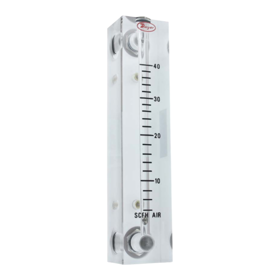
Model VFB
The Series VF Visi-Float
Flowmeters are furnished in two models (see drawing
®
above) each available in a broad choice of flow ranges with direct reading scales for
air, gas or water. Installation, operation and maintenance are very simple and only a
few common sense precautions must be observed to assure long, trouble-free service.
CALIBRATION
Each flowmeter is calibrated at the factory. If at any time during the meter's life, you
wish to recheck its calibration, do so only with devices of certified accuracy. DO NOT
attempt to check the Visi-Float
unimportant variations in piping and back pressure may cause noticeable differences
in the indicated reading. If in doubt, return your flowmeter to the factory. Before
proceeding with the installation of your Visi-Float
have the model and flow range you require.
LOCATION
Temperature, Pressure, Atmosphere, and Vibration:
Visi-Float
Acrylic Flowmeters are exceptionally tough and strong. They are designed
®
for use at pressures up to 100 psi (7 bar) and temperatures up to 150°F (66°C).
DO NOT EXCEED THESE LIMITS! The installation should not be exposed to strong
chlorine atmospheres or solvents such as benzene, acetone, carbon tetrachloride, etc.
The mounting panel should be free of excessive vibration since it may prevent the unit
from operating properly.
Inlet Piping Run: It is good practice to approach the flowmeter inlet with as few
elbows and restrictions as possible. In every case the inlet piping should be at least as
large as the connection to the flowmeter i.e. 1/8˝ Iron Pipe Size. Length of inlet piping
makes little difference for normal pressure fed flowmeters.
For flow meters on vacuum air service the inlet piping should be as short and open as
possible. This will allow operation near atmospheric pressure and thereby insure the
accuracy of the device. (Note that for vacuum air service the flow control valve if any,
should be on the discharge side of the flowmeter. Either the TMV unit or a separate in
line valve may be applied.)
Discharge Piping: As on the inlet, discharge piping should be at least as large as the
flowmeter connection. In addition, for pressure fed flowmeters on air or gas service the
discharge piping should be as short and open as possible. This will allow operation
of the flow tube at near atmospheric pressure and insure the accuracy of the device.
This is of less importance on water or liquid flowmeters since the flowing medium is
generally incompressible and moderate back pressure will not affect the accuracy of
the instrument as calibrated.
Find Quality Products Online at:
Series VF Visi-Float
Specifications - Installation and Operating Instructions
Model VFA-SSV
®
Flowmeter with a similar flowmeter as seemingly
Flowmeter, check to be sure you
®
GlobalTestSupply
www.
Flowmeters
®
A
B
D
SPECIFICATIONS
Service: Compatible gases and liquids.
Wetted Materials: Body: Acrylic plastic; O-ring: Buna-N (fluoroelastomer available);
Metal parts: brass standard, SS optional; Float: SS, black glass, aluminum, K monel
depending on range.
Temperature and Pressure Limits: Without valve: 100 psig (6.9 bar) @ 150°F
(65°C); 150 psig (10 bar) @ 100°F (38°C); With valve: 100 psig (6.9 bar) @ 120°F
(48°C).
Accuracy: VFA = 5% FS; VFB= 3% FS.
Process Connection: 1/8˝ female NPT. VFB ranges 85 and 86 have 1/4˝ NPT back
connections or 3/8˝ NPT end connections. These ranges not available with brass
valves.
Scale Length: VFA 2˝ typical length; VFB 4˝ typical length.
Mounting Orientation: Mount in vertical position.
Weight: VFA: 4.0-4.8 oz (.11-.14 kg). VFB: 7.2-8.8 oz (.20-.25 kg).
DIMENSIONS - FLOWMETER
Model VFA
A
4 [101.6]
B
3 [76.20]; 1/8 NPT conn.
C
1-5/8 [41.28]; 10-32 thd
D
1/2 [12.70]
E
1-3/16 [30.16]
F
1-1/4 [31.75]
I
2-1/16 [52.39]; Open
K
4-3/32 [104.0]
L
1 [25.40]
M
7/8 [22.23] ; 1/8 NPT
N
3/32 [2.381]
POSITION AND MOUNTING
All Visi-Float
Flowmeters must be mounted in a vertical position with the inlet
®
connection at the bottom and outlet at the top.
Surface Mounting: Drill appropriate holes in panel using the dimensions shown in
the drawing above. Hold the flowmeter in position in front of the panel and install the
mounting screws through the panel from the rear. Mounting screws must not be longer
than the panel thickness plus 1/4˝, or the screw will hit the plastic and may damage
the meter. The screws will require additional force during the initial installation, since
the insert boots are of a collapsed thread type and must be expanded into the plastic
for the knurled surface to take hold. Insert boots will not have the proper 10-32 threads
until the first screw has been inserted to expand the boot. Pipe up inlet and discharge
using pipe thread sealant tape or pipe thread sealant to insure against leakage.
F
M
K
C
E
M
I
FULL OPEN
Model VFB
6-1/2 [165.1]
5-1/2 [139.7]; 1/8 NPT conn.
3-1/2 [88.90]; 10-32 thd
1/2 [12.70]
1-1/2 [38.10]
1-1/4 [31.75]
2-1/16 [52.39] ; Open
6-11/16 [169.9]
1-3/8 [34.93]
7/8 [22.23]; 1/8 NPT
3/32 [2.381]
.com
sales@GlobalTestSupply.com
Bulletin F-33
L
N
Advertisement

Subscribe to Our Youtube Channel
Related Manuals for Dwyer Instruments Visi-Float VF Series


Summary of Contents for Dwyer Instruments Visi-Float VF Series
- Page 1 Bulletin F-33 Series VF Visi-Float Flowmeters ® Specifications - Installation and Operating Instructions Model VFB Model VFA-SSV FULL OPEN The Series VF Visi-Float Flowmeters are furnished in two models (see drawing ® SPECIFICATIONS above) each available in a broad choice of flow ranges with direct reading scales for Service: Compatible gases and liquids.
- Page 2 For additional flowmeter application information, conversion curves, factors and other extrapolation of the float location must be made by the operator as to its location data covering the entire line of Dwyer Instruments, Inc. full-line catalog. between the two closest grads. The following are some sample floats shown with reference to the proper location to read the float.
Need help?
Do you have a question about the Visi-Float VF Series and is the answer not in the manual?
Questions and answers