Table of Contents
Advertisement
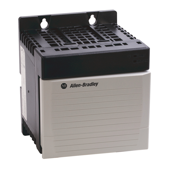
ControlLogix Redundant Power Supply
Catalog Numbers 1756-PA75R/A (85-265V AC Redundant Power Supply),
Use this publication as a guide when installing the ControlLogix™ 1756-PA75R/A
and 1756-PB75R/A power supplies. These supplies may only be used with Series B
ControlLogix chassis.
To:
See 1756-PA75R/A and 1756-PB75R/A Specifications
1756-PB75R/A (19-32V DC Redundant Power Supply)
Installation Instructions
See page:
10
11
13
14
15
16
17
18
18
19
20
21
22
6
6
6
7
8
9
Advertisement
Table of Contents

Related Manuals for Allen-Bradley ControlLogix 1756-PA75R/A


Summary of Contents for Allen-Bradley ControlLogix 1756-PA75R/A
-
Page 1: Table Of Contents
Route Line Power and Cables Remove the Protective Label Activate the Redundant Power Supply System See Input Power Requirements and Transformer Sizing Troubleshoot with the Status Indicators Replace a Redundant Power Supply Allen-Bradley H See 1756-PA75R/A and 1756-PB75R/A Specifications Publication 1756-IN573C-EN-P - October 2003... - Page 2 ControlLogix Redundant Power Supply Important User Information Solid state equipment has operational characteristics differing from those of electromechanical equipment. Safety Guidelines for the Application, Installation and Maintenance of Solid State Controls (Publication SGI-1.1 available from your local Rockwell Automation sales office or online at http://www.ab.com/manuals/gi) describes some important differences between solid state equipment and hard-wired electromechanical devices.
- Page 3 NOTE: See NEMA Standards publication 250 and IEC publication 60529, as applicable, for explanations of the degrees of protection provided by different types of enclosure. Also, see the appropriate sections in this publication, as well as the Allen-Bradley publication 1770-4.1 ("Industrial Automation Wiring and Grounding Guidelines"), for additional installation requirements pertaining to this equipment.
- Page 4 • This equipment shall be used within its specified ratings defined by Allen-Bradley. • Provision shall be made to prevent the rated voltage from being exceeded by transient disturbances of more than 40% when applied in Class I, Zone 2 environments.
- Page 5 Classe I, Division 2. • S’assurer que nonhazardous. l’environnement est Allen-Bradley H classé non dangereux avant de changer les piles. Publication 1756-IN573C-EN-P - October 2003...
-
Page 6: See A Description Of The Redundant Power Supply
ControlLogix Redundant Power Supply Description of the Redundant Power Supply These supplies are part of a redundant power supply system that provides additional uptime protection for a chassis used in critical applications. The two remotely-mounted supplies are designed to share the current required by the chassis. -
Page 7: Identify The Components Of A Redundant Power Supply System
Optional user-provided annunciator wiring can be connected to the solid state relay for status and troubleshooting purposes. For more information, see pages 15 and 20. The components are shown below in a typical system configuration: Figure 2 1756-PA75R/A 1756-PA75R/A Annunciator wiring 1756-CPR2 1756 Input module 1756-PSCA2 42655 Allen-Bradley H Publication 1756-IN573C-EN-P - October 2003... -
Page 8: Recognize Redundant Power Supply Physical Features
ControlLogix Redundant Power Supply Recognize Redundant Power Supply Physical Features Your redundant power supply has multiple physical features as shown below. Figure 3 Diagnostic LEDs Supply shown ON/OFF switch without door or label. Solid state relay connections Power input Plastic barrier connections 42656 Male cable... -
Page 9: Use System Set-Up Recommendations
We recommend you use one of the methods shown below when setting up your redundant power supply system. Figure 4 Recommended Set-Ups for System Using One Chassis 42655 42657 Recommended Set-Ups for System Using Two Chassis 42655 Allen-Bradley H 42658 42655 Publication 1756-IN573C-EN-P - October 2003... -
Page 10: Allow Sufficient Mounting Space
ControlLogix Redundant Power Supply Allow Sufficient Mounting Space Make sure you meet these minimum spacing requirements: IMPORTANT • 10.2cm (4in) between redundant power supplies and cabinet housing the control system • 2.55cm (1in) between redundant power supplies • 15.3cm (6in) between chassis and heat source •... -
Page 11: Install Your Redundant Power Supply
The 1756-PA75R/A and 1756-PB75R/A power supplies use the same mounting dimensions as the 1756-A4 chassis. 2. Drill holes in the back panel of the enclosure for redundant power supply mounting tabs. Figure 7 20288 Allen-Bradley H Publication 1756-IN573C-EN-P - October 2003... - Page 12 ControlLogix Redundant Power Supply 3. Install the hardware for the top mounting tabs. Figure 8 #10 phillips screw 42664 4. Slide the redundant power supply over the installed screws and tighten them. Figure 9 42659 5. Install the remaining tab screw(s). Figure 10 31175 Publication 1756-IN573C-EN-P - October 2003...
-
Page 13: Ground Your Redundant Power Supply
• Use a ground bus to reduce the electrical resistance at the connection. • Keep wire lengths as short as possible. • Use 14 AWG (2.08 sq. mm) 75°C stranded wire for ground connections. Figure 11 Allen-Bradley H 42661 Earth Ground Publication 1756-IN573C-EN-P - October 2003... -
Page 14: Connect The Cable To The Redundant Power Supply And The Chassis
ControlLogix Redundant Power Supply Connect the Cable to the Redundant Power Supply and the Chassis Adapter Module Use the 1756-CPR2 cable to connect your redundant power supply to the chassis adapter module. The 1756-CPR2 cable uses two female ends to connect to male connectors on the redundant power supply and the chassis adapter module. -
Page 15: Connect Solid State Relay
The annunciator cable must not exceed 10 meters (32.8 feet). For recommendations on how to route the wiring in your redundant power supply application, see page 17. Allen-Bradley H Publication 1756-IN573C-EN-P - October 2003... -
Page 16: Connect Power
ControlLogix Redundant Power Supply Connect Power Turn off power lines before connecting power; failure to do so ATTENTION could cause injury to personnel and/or equipment. This equipment must be provided with a disconnect on each ungrounded conductor. We recommend using #14 AWG (2.08 sq. mm) 75°C copper stranded wire to connect power to each redundant power supply. -
Page 17: Route Line Power And Cables
Figure 17 In this case, make sure you tuck the annunciator wiring under the tab at the top of the plastic barrirer. Plastic barrier To AC input power Allen-Bradley H Annunciator cable Output power to DC input module (1756-CPR2) to chassis... -
Page 18: Remove The Protective Label
ControlLogix Redundant Power Supply Remove the Protective Label Make sure the power supply is mounted and all panel ATTENTION fabrication is complete before you remove the protective label. This label protects the power supply from metal shavings falling inside the power supply. Pull the label off the power supply. -
Page 19: See Input Power Requirements And Transformer Sizing
(Watts) 43588 real power (Watts) apparent power (Watts) transformer load (VA) = real power (Watts) Power factor circuitry reduces transformer sizing requirements. 1756-PB75R/A (dc) backplane Allen-Bradley H power load (Watts) 43589 real power (Watts) Publication 1756-IN573C-EN-P - October 2003... -
Page 20: Troubleshoot With The Status Indicators
ControlLogix Redundant Power Supply Troubleshoot with the Status Indicators Your redundant power supply uses the following diagnostic status indicators (LEDs) • Power - Green • Non-red (non-redundancy) - Amber to display possible problems with the supply. At initial power-up, the Power indicator is illuminated. -
Page 21: Replace A Redundant Power Supply
4. Connect all cables to the new supply as described on pages 14-17. 5. Activate power as described on page 18. When you turn ON the replacement redundant power supply, the connected chassis automatically draws power from both redundant power supplies. Allen-Bradley H Publication 1756-IN573C-EN-P - October 2003... -
Page 22: Publication 1756-In573C-En-P - October
ControlLogix Redundant Power Supply 1756-PA75R/A and 1756-PB75R/A Specifications 1756-PA75R/A 1756-PB75R/A Location Near ControlLogix chassis Input Voltage Range 85-265V ac 19.2-32V dc 120VA, 115W 110W Input Power Output Power 75W @ 60°C (Do not exceed 75W) 1.5 A @ 1.2 V Maximum Backplane Output Current 4 A @ 3.3 V 13 A @ 5.1 V... - Page 23 >95% interuptions for 250 periods on AC supply ports" "60% dips for 100ms on DC supply ports 100% dips for 50ms on DC supply ports ±20% fluctuations for 15min on DC supply ports 5sec interruptions on DC supply ports Allen-Bradley H Publication 1756-IN573C-EN-P - October 2003...
- Page 24 1756-PA75R/A 1756-PB75R/A Certifications: The following certifications apply to both power supplies: (when product is marked) UL Listed Industrial Control Equipment c-UL-us UL Listed for Class I, Division 2 Group A,B,C,D Hazardous Locations, certified for U.S. and Canada CSA CSA Certified Process Control Equipment CSA CSA Certified Process Control Equipment for Class I, Division 2 Group A,B,C,D Hazardous Locations FM Approved Equipment for use in Class I Division 2...
Need help?
Do you have a question about the ControlLogix 1756-PA75R/A and is the answer not in the manual?
Questions and answers