Advertisement
Quick Links
To the Installer
Prepare for Installation
Install the Power Supply and
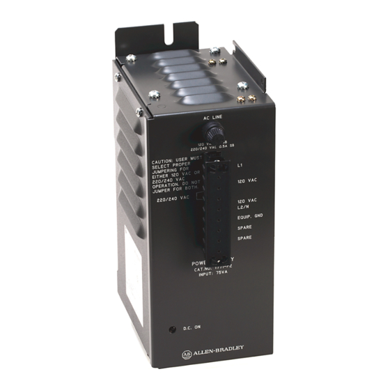
Connect Backplane Power
9 pin plugs
Labels on each plug
identify proper connection.
1771 CE or CD cable
19568
Auxiliary Power Supply
(Cat. No. 1771-P2)
Installation Data
This document provides information on:
preparing to install the power supply
installing the power supply
connecting ac power to the power supply
power supply output
troubleshooting
specifications
The auxiliary power supply can power one bulletin 1771 I/O chassis
when used with an adapter module, a 1772 Mini-PLC-2
®
1772 Mini-PLC-2/15
The auxiliary power supply does not provide battery backup. For battery
backup, use a system power supply (cat. no. 1771-P1).
If You Are Mounting the Power Supply:
on the left side of the chassis
within 5 cable feet of the I/O chassis
If you mount the power supply on the left side-plate of the I/O chassis,
mount the I/O chassis first (if you have not already done so). See the
Universal I/O Chassis Installation Data (publication 1771-2.210) for
information on mounting the I/O chassis.
When mounted separately, the power supply can be mounted above or next
to the I/O chassis. It can not be mounted below since it is necessary to
allow convection cooling of both the power supply and the I/O chassis.
A minimum vertical distance of six inches should be maintained.
processor.
Use this Power Cable (Cat. No.):
®
processor, or a
1771 CE
1771 CD
Advertisement

Subscribe to Our Youtube Channel
Related Manuals for Allen-Bradley 1771-P2


Summary of Contents for Allen-Bradley 1771-P2
- Page 1 Auxiliary Power Supply (Cat. No. 1771-P2) Installation Data To the Installer This document provides information on: preparing to install the power supply installing the power supply connecting ac power to the power supply power supply output troubleshooting specifications Prepare for Installation The auxiliary power supply can power one bulletin 1771 I/O chassis ®...
- Page 2 Installation Data Auxiliary Power Supply Cat. No. 1771 P2 Mount the Power Supply ATTENTION: If you do not remove system power, you could damage the module circuitry and/or cause undesired operation with possible injury to personnel. Remove system power. Mount the power supply. If Mounting Separately: If Mounting on Left Side of Chassis: Mount the power supply up to 5 cable feet...
- Page 3 Manufacturer's No. 120V ac Bussman: MDL 1A Littelfuse: 313001 220/240V ac Bussman: MDL 0.5A 0.5A Littelfuse: 313.500 A replacement fuse kit (cat. no. 1771-FP) containing both 1A and 0.5A fuses is available. Contact your local Allen-Bradley representative for further information.
- Page 4 Backplane Load Current (Amps) Apparent Power (VA) Real Power (Watts) Transformer Sizing (VA) = Real Power (Watts) x 2.5 PLC-2 and PLC-2/15 are registered trademarks of Allen-Bradley Company, Inc.
Need help?
Do you have a question about the 1771-P2 and is the answer not in the manual?
Questions and answers