Advertisement
Quick Links
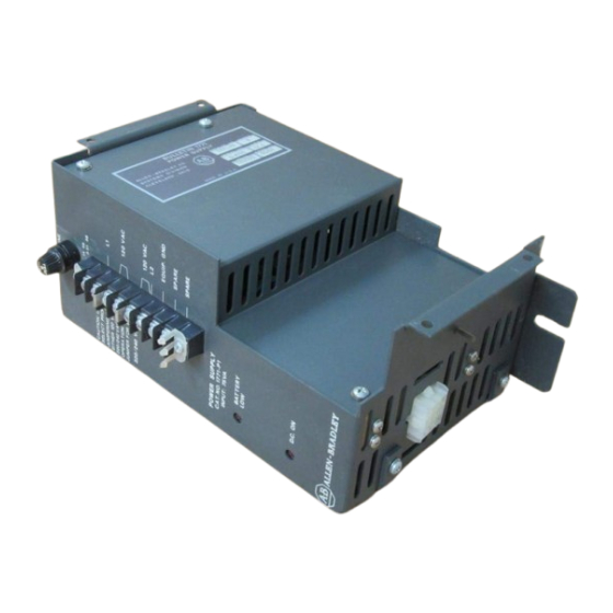
(Cat. No. 1771-P1)
Installation Data
Use this publication to install a 1771-P1 system power supply.
You perform these tasks:
prepare to install the power supply
- install batteries into the battery pack
- install the battery-pack housing
install the power supply
- mount the power supply
- connect backplane power
- install the battery pack
connect ac power to the power supply
You must use the 1771-P1 to power these programmable controllers:
1772 Mini-PLC-2 processor
1772 Mini-PLC-2/15 processor
The power supply provides a regulated 5.1V dc for the logic circuitry of
the processor and I/O modules in the chassis.
If you are installing the power supply on the left side-plate of an I/O
chassis, you must:
install batteries into the battery pack
install the battery-pack housing
Advertisement

Related Manuals for Allen-Bradley 1771-P1


Summary of Contents for Allen-Bradley 1771-P1
- Page 1 (Cat. No. 1771-P1) Installation Data Use this publication to install a 1771-P1 system power supply. You perform these tasks: prepare to install the power supply - install batteries into the battery pack - install the battery-pack housing install the power supply...
- Page 2 The 1771-P1 comes with a separate battery pack that supplies memory backup power if the power supply shuts down due to loss of ac power on the input line or any other condition. You can use: The alkaline battery provides reliable memory backup at low cost.
- Page 3 The battery pack, mounted on the side of the I/O chassis, provides a compact housing for the batteries. Use the hardware provided to install the mounting brackets onto the left side of the I/O chassis. If you mount the power supply on the left side-plate of the I/O chassis, mount the I/O chassis first (if you have not already done so).
- Page 4 ATTENTION: If you do not remove system power, you could damage the module circuitry and/or cause undesired operation with possible injury to personnel. Remove system power. Mount the power supply.
- Page 5 Connect one 9-pin plug of the power cable to the 9-pin connector located on the bottom of the power supply. Connect the other 9-pin plug to the external power supply connector on the I/O chassis. To make this connection, remove the mini-processor module and left-most I/O module from the I/O chassis.
- Page 6 Connect the 3-pin plug to the socket at the base of the battery pack. Align the battery pack with the card guides and slide it into the battery-pack housing. Tighten the thumbscrew on the battery pack to secure it in the bracket.
- Page 7 220/240V operation, remove the 1A fuse and replace it with the 0.5A slow-blow fuse that is provided. Replacement fuses are shown below: A replacement fuse kit (cat. no. 1771-FP) containing both 1A and 0.5A fuses is available. Contact your local Allen-Bradley representative for further information.
- Page 8 The power supply monitors input voltage for proper operating levels. AC input line connections for either 120V ac or 220/240V ac are made to the terminals marked L1 and L2. Use the grounding stud located on the bottom of the power supply to connect the power supply to the system ground bus.
- Page 9 If this occurs, cycle ac power to the supply. To do this, disconnect and then reconnect user line power, preferably from the user-supplied main disconnect switch, mounted near the power supply. The power supply has these LED indicators: ’s For additional assistance, contact your local Allen-Bradley representative.
- Page 10 RayOVac is a registered trademark of RayOVac Corporation. As a subsidiary of Rockwell International, one of the world’s largest technology companies — Allen-Bradley meets today’s challenges of industrial automation with over 85 years of practical plant-floor experience. More than 11,000 employees throughout the...
Need help?
Do you have a question about the 1771-P1 and is the answer not in the manual?
Questions and answers