Advertisement
Quick Links
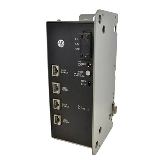
(Cat. No. 1771-PS7 Series C)
Installation Data
Use this publication to install a 1771-PS7 external power supply.
You perform these tasks:
prepare to mount the 1771-PS7
mount the 1771-PS7 and connect backplane power
connect user power to modules (optional)
connect ac power source to the 1771-PS7
The 1771-PS7 provides:
ATTENTION: To avoid overloading the power supply:
limit backplane power to 80W, or
limit user power to 65W, or
limit total system power (backplane + user) to 100W
Advertisement

Related Manuals for Allen-Bradley 1771-PS7 С Series


Summary of Contents for Allen-Bradley 1771-PS7 С Series
- Page 1 (Cat. No. 1771-PS7 Series C) Installation Data Use this publication to install a 1771-PS7 external power supply. You perform these tasks: prepare to mount the 1771-PS7 mount the 1771-PS7 and connect backplane power connect user power to modules (optional) connect ac power source to the 1771-PS7 The 1771-PS7 provides: ATTENTION: To avoid overloading the power supply: limit backplane power to 80W, or...
- Page 2 Before mounting the 1771-PS7, you should: mount the I/O chassis. See the Universal I/O Chassis Installation Data (1771-2.210) for information on mounting the I/O chassis. set the power supply configuration jumper. The 1771-PS7 is an external power supply. Set the configuration jumper on the I/O chassis to the N position.
- Page 3 To attach the 1771-PS7 to a panel-mounted chassis: Remove the four #10-32 nuts and separate the mounting plate from the power supply. Use four 0.312-inch screws (#10-32) and washers to install the mounting plate onto the side plate of the I/O chassis. ATTENTION: Do not use screws longer than 0.312 inch to mount the 1771-PS7 to the I/O chassis.
- Page 4 Install the supplied alignment fixture onto the taper pins of the mounting plate (moving mounting plate as necessary) and push until the alignment fixture is fully inserted into the receptacle on the chassis. Tighten the #10-32 screws to permanently attach the mounting plate to the I/O chassis.
- Page 5 Align the receiving holes of the power supply over the taper pins on the mounting plate and push until the plug on the power supply is fully inserted into the receptacle on the chassis. Install four #10-32 nuts supplied onto the #10-32 studs now protruding through the power supply mounting holes from the mounting plate.
- Page 6 When mounted separately, the 1771-PS7 may be mounted above or next to the I/O chassis. It may not be mounted below, since it is necessary to allow convection cooling of both the power supply and the I/O chassis. A minimum vertical distance of six inches should be maintained. To attach the 1771-PS7 to a rack-mounted I/O chassis (1771-A3B): Mount the 1771-PS7 vertically, above and within the specified cable-feet (for your cable) of the D-sub connector on the top of the...
- Page 7 Connect one end of the power cable to the D-sub connector located on the side of the 1771-PS7 power supply and tighten the connector screws. Connect the other end of the power cable to the D-sub connector located on the top of the chassis and tighten the connector screws.
- Page 8 To connect the 1771-PS7 to an IMC 120, 120AR, 121 or 123 motion-controller module and a resolver-excitation module: Make sure the power switch is set to OFF. Connect one end of a 1771-CAS cable: to a user power connector on the 1771-PS7 to the axis on the controller module...
- Page 9 The following figure shows physical dimensions and wiring details for the 1771-CAS cable. µ µ To connect the 1771-PS7 to non-IMC products, you must modify a 1771-CAS cable. Cut the cable as short as possible to minimize voltage losses. Double-up on +24V dc, +5V dc, +24V dc common, +5V dc common and 15V dc commons on each connector, as shown:...
- Page 10 The 1771-PS7 requires input from a 120V ac or 220V ac source. As a safety precaution, the 1771-PS7 is shipped with the input voltage selector switch set to 220V. To connect power to the 1771-PS7: Make sure the power switch is set to OFF. Use a 1/8”...
- Page 11 (backplane + user) > 100W total user power > 65W total +5V user power > 40W input voltage level not within specified range power supply is inoperative blown fuse For additional assistance, contact your local Allen-Bradley representative.
- Page 12 As a subsidiary of Rockwell International, one of the world’s largest technology companies — Allen-Bradley meets today’s challenges of industrial automation with over 85 years of practical plant-floor experience. More than 11,000 employees throughout the world design, manufacture and apply a wide range of control and automation products and supporting services to help our customers continuously improve quality, productivity and time to market.
Need help?
Do you have a question about the 1771-PS7 С Series and is the answer not in the manual?
Questions and answers