Table of Contents
Advertisement
Quick Links
The SOR
®
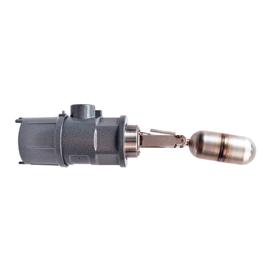
1710 Side Mounted Level Switch is a horizontally mounted, float-operated
level switch. The 1710 is suitable for plant and OEM applications where open or closed
contacts are required to signal presence or absence of liquid at a discrete level.
When the liquid rises, the float extension arm moves a magnet which repels an internal
magnet de-actuating a microswitch. When the liquid level falls, the float extension arm
moves the magnet in the opposite direction, actuating the microswitch.
The 1710 is recommended for use in clean liquids only.
NOTE: If you suspect that a product is defective, contact the factory or the SOR Representative
in your area for a return authorization number (RMA). This product should only be installed by
trained and competent personnel.
Design and
specifications are
subject to change
without notice.
For latest revision, go to
SORInc.com
Form 916 (06.18) ©SOR Inc.
1710
Physical Installation ............................2
Electrical Installation ..........................3
SIL Installation Requirements ................3
Dimensions ......................................4
Replacement Switch Assemblies ............4
ATEX Information ...............................5
Declaration of Conformity .....................7
Maintenance .....................................8
Troubleshooting .................................8
Registered Quality System to ISO 9001
Side Mounted
Level Switch
General Instructions
Table of Contents
1/8
Advertisement
Table of Contents

Subscribe to Our Youtube Channel
Related Manuals for SOR 1710


Summary of Contents for SOR 1710
-
Page 1: Table Of Contents
® 1710 Side Mounted Level Switch is a horizontally mounted, float-operated level switch. The 1710 is suitable for plant and OEM applications where open or closed contacts are required to signal presence or absence of liquid at a discrete level. -
Page 2: Physical Installation
Physical Installation The 1710 must be mounted so that the centerline is within 3º of horizontal. The conduit connection centerline must be within 3° of vertical and the nameplate at 12 o’clock. Switch actuation cannot be reversed by rotating the unit 180°. -
Page 3: Electrical Installation
LEVEL HIGH Safety Integrity Level (SIL) Installation Requirements The SOR pressure switches have been evaluated as Type-A safety related hardware. To meet the necessary installation requirements for the SIL system, the following information must be utilized: Proof Test Interval shall be one year. -
Page 4: Dimensions
Components to be incorporated into or used as replacement parts of the equipment shall be fitted by suitably-trained personnel in accordance with the manufacturer’s documentation (or inform of contracting manufacturer or their stockist or specify no replaceable component parts). Form 916 (06.18) ©SOR Inc. -
Page 5: Atex Information
IIC or IIB + Hydrogen (see product nameplate) and with temperature class T5 in the ambient temperature range -40ºC to +80ºC. The equipment is only certified for use in ambient temperatures in the range -40ºC to +80ºC and should not be used outside this range. Form 916 (06.18) ©SOR Inc. - Page 6 (96) (88) (82) (78) (75) 4” S40 1435 1435 1435 1435 1435 1435 1378 316/316L SS (99) (99) (99) (99) (99) (99) (95) Electrical and Pressure Paramaters Switch Rating 6A, 125/250 VAC 1/2A, 28 VDC Form 916 (06.18) ©SOR Inc.
-
Page 7: Declaration Of Conformity
Declaration of Conformity For ATEX Certified Models Form 916 (06.18) ©SOR Inc. -
Page 8: Maintenance
The float is leaky or collapsed. Contact the factory. Printed in USA SORInc.com 14685 West 105th Street, Lenexa, KS 66215 913-888-2630 800-676-6794 USA Fax 913-888-0767 Registered Quality System to ISO 9001 Form 916 (06.18) ©SOR Inc.
Need help?
Do you have a question about the 1710 and is the answer not in the manual?
Questions and answers