Table of Contents
Advertisement
Quick Links
®
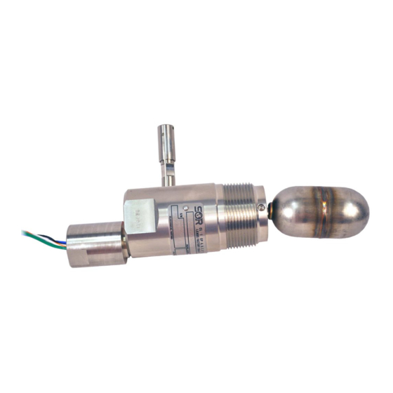
The SOR
1510 Level Switch mounts into the side of a vessel. Electric switching action is
provided by the float moving a magnet into the field of a hermetically sealed reed switch
capsule.
The unit may be mounted for either high or low liquid level alarm by rotating the switch
body to the proper position. The body wrench flats provide for ease of rotation and proper
positioning. See decal on housing.
Before Installation of the Level Switch:
Inspect the unit for any shipment damage.
Check for mechanical clearance of
the float. Float must move freely without binding throughout its stroke.
Use an acceptable thread compound when installing unit to ensure a leak-free fit and to
avoid thread galling.
To achieve required function, install the unit according to the nameplate instructions
shown here.
NOTE: If you suspect that a product is defective, contact the factory or the SOR Representative
in your area for a return authorization number (RMA). This product should only be installed by
trained and competent personnel.
THIS SIDE UP
N.C. @ LOW LEVEL
Nameplate Position
for Low Level Alarm
Design and
specifications are
subject to change
without notice.
For latest revision, go to
www.SORInc.com
Form 451 (05.18) ©SOR Inc.
1510
rench flats provide for ease of rotation and proper
ma a ge.
THIS SIDE UP
N.C. @ HIGH LEVEL
Nameplate Position
for High Level Alarm
Installation ...................................... 3
SIL Installation Instructions .................. 3
Float Attachment ............................... 3
Dimensions ..................................... 4
Electrical Connection .......................... 5
Special Conditions ............................. 5
Wiring for DPDT Relay ........................ 6
ATEX and IECEx Marking Details ............ 6
Declaration of Conformity .................... 7
Troubleshooting ................................ 8
Replacement Parts ............................ 8
Registered Quality System to ISO 9001
Side Mounted
Level Switch
General Instructions
NC - indicates
circuit is closed
Table of Contents
1/8
Advertisement
Table of Contents

Subscribe to Our Youtube Channel
Related Manuals for SOR 1510


Summary of Contents for SOR 1510
-
Page 1: Table Of Contents
To achieve required function, install the unit according to the nameplate instructions shown here. NOTE: If you suspect that a product is defective, contact the factory or the SOR Representative in your area for a return authorization number (RMA). This product should only be installed by trained and competent personnel. -
Page 2: Installation
At the bottom of the cable, a second loop can be created as a handle for actuation at the desired length. Linear = mm/inches Drawing 0098636 PLUNGER TOP 14” LOOP REMOTE CABLE REMOTE MANUAL CHECK MD OPTION CRIMP CREATE HANDLE AT DESIRED LENGTH Form 451 (05.18) ©SOR Inc. -
Page 3: Sil Installation Instructions
Safety Integrity Level (SIL) Installation Requirements The SOR pressure switches have been evaluated as Type-A safety related hardware. To meet the necessary installation requirements for the SIL system, the following information must be utilized: Proof Test Interval shall be one year. -
Page 4: Dimensions
79.0 REF 7.00 3.11 NOTES: 1. ACTUATE / DEACTUATE POINTS VARY. OPERATES 56.4 SATISFACTORILY IN 2" FULL COUPLING ( 2.22 Dimensions are for reference only. Contact the factory for certified drawings for a particular model number. Form 451 (05.18) ©SOR Inc. -
Page 5: Electrical Connection
IP20. When marked and installed as Ex d equipment, the permanently attached leads must be suitably protected against mechanical damage and terminated in a suitable junction box or terminal facility. Form 451 (05.18) ©SOR Inc. -
Page 6: Wiring For Dpdt Relay
For Type 1510 Level Switches equipped with DPDT relays, a wiring schematic and pin position schematic is shown below. When the 1510 is actuated, the coil will energize and “make” both NO1 and NO2 while it will “break” NC1 and NC2. This provides a DPDT circuit. -
Page 7: Declaration Of Conformity
Declaration of Conformity For ATEX Certifi ed Models Form 451 (05.18) ©SOR Inc. -
Page 8: Troubleshooting
* Unit must have originally been supplied with MC or MD option. SORInc.com 14685 West 105th Street, Lenexa, KS 66215 913-888-2630 800-676-6794 USA Fax 913-888-0767 Registered Quality System to ISO 9001 Form 451 (05.18) ©SOR Inc.
Need help?
Do you have a question about the 1510 and is the answer not in the manual?
Questions and answers