Table of Contents
Advertisement
Quick Links
These instructions provide specific information for installation,
electrical connection, calibration and troubleshooting for the
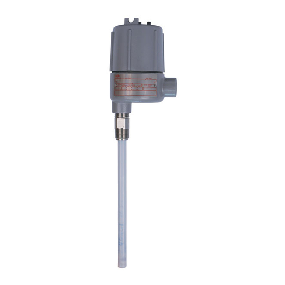
651 K9 RF Admittance Two-Wire Point Level Control.
NOTE: If you suspect that a product is defective, contact the factory
or the SOR
®
Representative in your area for a return authorization
number. This product should only be installed by trained and
competent personnel.
Pre-Installation I/O Test and Calibration
Remove the housing cover.
Place the instrument on an insulated surface or support
so the sensor does not touch a conductive surface.
Apply 12 to 28VDC, and observe the LED. (See
NOTE: When the LED is on, it indicates the output is in the normal state 16-20mA.
Turn the sensitivity adjustment clockwise (up to 25 turns) to increase sensitivity until
the LED goes out.
NOTE: Do not turn the sensitivity adjustment past 25 turns! Damage to the unit could result.
Turn the sensitivity adjustment counterclockwise to decrease sensitivity until the
LED illuminates.
Design and
specifications are
subject to change
without notice.
For latest revision, go to
SORInc.com
Form 759 (04.16) SOR Inc.
651 K9 RF Admittance
Two Wire Point Level Control
on page 2)
Pre-Installation I/O and Calibration ....... 1-2
Installation .......................................3
Electrical Connections .........................4
Post-Installation Calibration ..................4
SOR RF Probe Grounding Screen ............5
Control Drawings ............................ 6-9
Instructions for EMC .......................... 10
Spare Parts .................................... 10
Information for IEC-Listed Product ......... 10
Maintenance and Troubleshooting ......... 11
Dimensions ................................ 12-13
ATEX and IECEx Marking Details ........... 14
Declaration of Conformity ................... 15
Registered Quality System to ISO 9001
General Instructions
Table of Contents
1/16
Advertisement
Table of Contents

Subscribe to Our Youtube Channel
Related Manuals for SOR 651 K9 RF


Summary of Contents for SOR 651 K9 RF
-
Page 1: Table Of Contents
General Instructions These instructions provide specific information for installation, electrical connection, calibration and troubleshooting for the 651 K9 RF Admittance Two-Wire Point Level Control. NOTE: If you suspect that a product is defective, contact the factory or the SOR ®... - Page 2 To detect an interface, such as oil/water or foam/liquid, the lighter material must be in contact with the sensor, then tuned out. Then adjust the sensitivity to detect the heavier process material. (See Water 2/16 Form 759 (04.16) SOR Inc.
-
Page 3: Installation
Optional confi guration is a raised face or flat face ANSI flange. See Form 1100 for selection. (See Orientation. The control can be mounted in any position. Sensitivity is optimized when the greatest surface area of the sensor is parallel to the process level. (See 3/16 Form 759 (04.16) SOR Inc. -
Page 4: Electrical Connections
Raise the material level until it is above the sensing element. The LED should be off. Turn the adjustment slowly counter-clockwise until the LED illuminates. Then turn the adjustment 1/2 turn clockwise (LED off) to complete the calibration. 4/16 Form 759 (04.16) SOR Inc. -
Page 5: Sor Rf Probe Grounding Screen
SOR RF Probe Grounding Scheme Critical Grounding Path = Circuit Board Power Supply Line Line Neutral Neutral Ground Ground Electronics Housing Process Connection IMPORTANT! Do not provide separate earth grounding for the process SOR Supplied connection. This can create Stilling Well... -
Page 6: Control Drawings
Control Drawing Drawing 9093008 6/16 Form 759 (04.16) SOR Inc. - Page 7 Control Drawing Drawing 9093010 7/16 Form 759 (04.16) SOR Inc.
- Page 8 Control Drawing Drawing 9093011 8/16 Form 759 (04.16) SOR Inc.
- Page 9 Control Drawing Drawing 9093009 9/16 Form 759 (04.16) SOR Inc.
-
Page 10: Instructions For Emc
651K9, a shielded cable, cable gland, shield bead and the probe should be mounted in a metallic vessel. SOR recommends using a shielded cable made of PVC Insulation around a tinned copper braid Short/Fat Bead shield (Olflex CY cable or equivalent). -
Page 11: Maintenance And Troubleshooting
Call the factory. 23 mA Output current is below The oscillator is not Call the factory. 3.5 mA working. NOTE: Agency certifi ed units, (FM, CSA, IEC) must be returned to SOR for repairs. 11/16 Form 759 (04.16) SOR Inc. -
Page 12: Dimensions
3/4” NPT(M) 3.46 3.71 10.08 10.33 99.7 97.3 268.0 265.6 1, 1-1/2, & 2” NPT(M) 3.92 3.83 10.56 10.46 158.5 158.5 326.8 326.8 Flanged 6.24 6.24 12.87 12.87 120.0 288.3 Stilling Well 4.72 11.35 12/16 Form 759 (04.16) SOR Inc. - Page 13 Drawing 0390654 Dual Cable Probe Detail 3/4-16 UNF- 36.5 1.44 SEE DETAIL A 3/4-16 UNF-2B X 11.1 22.2 UAL CABLE PROBE DETAIL 27.0 0.44 0.88 1.06 31.8 1.25 Linear = mm/inches 54.0 2.13 Drawing 0390654 13/16 Form 759 (04.16) SOR Inc.
-
Page 14: Atex And Iecex Marking Details
General Information for ATEX Certifi ed Models Sample Nameplates Drawing 8924119 Manufacturer’s Location of Product Registered Model Identification Trademark Location of Serial Number (First Two Numbers Indicate Year of Manufacture) Drawing 0720527 Manufacturer’s Registered Trademark Location of ATEX Listing Information 14/16 Form 759 (04.16) SOR Inc. -
Page 15: Declaration Of Conformity
Declaration of Conformity For ATEX Certifi ed Models 15/16 Form 759 (04.16) SOR Inc. - Page 16 SORInc.com 14685 West 105th Street, Lenexa, KS 66215 913-888-2630 800-676-6794 USA Fax 913-888-0767 16/16 Registered Quality System to ISO 9001 Form 759 (04.16) SOR Inc.
Need help?
Do you have a question about the 651 K9 RF and is the answer not in the manual?
Questions and answers