Table of Contents
Advertisement
Quick Links
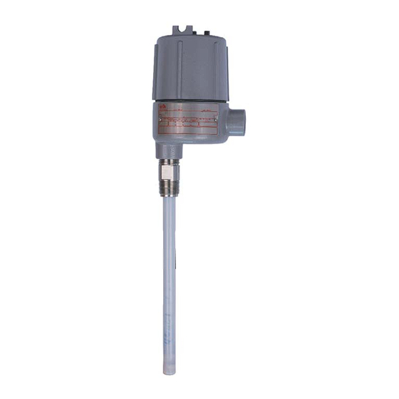
The 651 RF Admittance Single Point Level Switch is a level control which
uses dielectric constant and conductivity to detect the level of liquids,
slurries, granulars, and solids. When used with any of the RF Probes,
it will provide accurate switching for level processes.
The control features a fail-safe switch which reverses the operation of
the relay. An LED inside the housing lights when the process is touching
the probe. A sensitivity adjustment inside the control allows the user to
increase or decrease sensitivity as needed. Optional time delay feature
will delay switching on or off from 0 to 60 seconds.
NOTE: If you suspect that a product is defective, contact the factory or the
®
SOR
Representative in your area for a return authorization number (RMA).
This product should only be installed by trained and competent personnel.
Pre-Installation I/O Test and Calibration
Remove instrument from shipping box and visually inspect for obvious
physical damage. Report any shipping damage to the carrier. Report
any internal discrepancies to the factory representative in your area.
Record the serial number from the nameplate should conversation
with the factory be necessary.
Remove housing cover.
Place instrument on an insulated surface or support so sensor does not touch a
conductive surface.
Ensure area is safe and observe normal precautions for exposed and powered PC board.
Apply proper line power per page 4, and observe LED. (See
Design and
specifications are
subject to change
without notice.
For latest revision, go to
www.sorinc.com
Form 830 (03.13) ©SOR Inc.
651 RF Admittance
Single Point Level Switch
Installation .......................................3
Electrical Connections .........................4
RF Probe Grounding Scheme .................5
Fail-Safe Mode ..................................6
Circuit Board Replacement ....................7
Sensor Replacement ...........................7
Control Drawings ............................ 8-9
Troubleshooting ............................... 10
Dimensions ................................ 11-12
Registered Quality System to ISO 9001
General Instructions
h
g
).
ous
)
Table of Contents
1/12
Advertisement
Table of Contents

Related Manuals for SOR 651 Series


Summary of Contents for SOR 651 Series
-
Page 1: Table Of Contents
Fail-Safe Mode ........6 without notice. Circuit Board Replacement ....7 Sensor Replacement ......7 For latest revision, go to Control Drawings ......8-9 www.sorinc.com Troubleshooting ....... 10 Dimensions ........ 11-12 1/12 Form 830 (03.13) ©SOR Inc. Registered Quality System to ISO 9001... - Page 2 To detect an interface, such as oil/water or foam/liquid, the lighter material must be on the sensor, then tuned out. Then adjust the sensitivity to detect the heavier process material. (See 2/12 Form 830 (03.13) ©SOR Inc.
-
Page 3: Installation
It is permissible to increase sensor length by welding a length of identical rod to the supplied sensor. If the sensor is flexible cable, do not cut or modify it in any way, as sensor integrity will be compromised. 3/12 Form 830 (03.13) ©SOR Inc. -
Page 4: Electrical Connections
24 ± 10% VDC 50mA 12 ± 10% VDC 100 mA Ensure that wiring conforms to all applicable local and national electrical codes and install unit(s) according to relevant national and local safety codes. 4/12 Form 830 (03.13) ©SOR Inc. -
Page 5: Rf Probe Grounding Scheme
(typically red) to L2 position. Replace cover. Apply power as desired. Perform Steps 8 and 9 above. SOR RF Probe Grounding Scheme SOR RF Probe Grounding Scheme Critical Grounding Path = Circuit Board Power Supply Line Line... -
Page 6: Fail-Safe Mode
Connect line power supply as shown on pages 4 and 5. Continuity Chart Switch Position Process Level Terminal Continuity Fail Safe Relay Energized Relay de-energized on high level Relay De-Energized Fail Safe Relay De-Energized Relay de-energized on low level Relay Energized 6/12 Form 830 (03.13) ©SOR Inc. -
Page 7: Circuit Board Replacement
Replace the two mounting screws into the plastic ring. These screws are self-tapping. Do not overtighten. Replacement Circuit Boards can only be ordered from SOR. Match the first five characters of your model number with those shown below to select the proper replacement board part number. -
Page 8: Control Drawings
Control Drawing 8/12 Form 830 (03.13) ©SOR Inc. - Page 9 Control Drawing 9/12 Form 830 (03.13) ©SOR Inc.
-
Page 10: Troubleshooting
Eroded or abraded Fast flowing or agitated Consider other sensor material sensor process has physically or design, relocating sensor or a attacked sensor. stilling well in liquid process. 10/12 Form 830 (03.13) ©SOR Inc. -
Page 11: Dimensions
1, 1-1/2, & 2 NPTM 3.92 3.83 8.55 8.46 STILLING WELL 1.05 7.90 158.5 158.5 276.0 276.0 FLANGED CABLE 6.24 6.24 10.87 10.87 0.31 120.0 237.5 15.9 INACTIVE SHEATH STILLING WELL 4.72 9.35 0.63 11/12 Form 830 (03.13) ©SOR Inc. - Page 12 3/4-16 UNF-2B X 11.1 22.2 0.44 0.88 DETAIL A SCALE 1.5 Printed in USA www.sorinc.com 14685 West 105th Street, Lenexa, KS 66215 913-888-2630 800-676-6794 USA Fax 913-888-0767 12/12 Registered Quality System to ISO 9001 Form 830 (03.13) ©SOR Inc.
Need help?
Do you have a question about the 651 Series and is the answer not in the manual?
Questions and answers